Home › Vehicle Interior › HEATING / AIR CONDITIONING › AIR CONDITIONING UNIT (for LHD)
RM37H0E _58 Vehicle Interior _095300 HEATING / AIR CONDITIONING _0448173 AIR CONDITIONING UNIT(for LHD) A

HEATING / AIR CONDITIONING  AIR CONDITIONING UNIT(for LHD)  REASSEMBLY  


CAUTION / NOTICE / HINT
COMPONENTS (REASSEMBLY)
E458057N08
1.365,3.052 2.427,3.25 1.063,0.198 0.729,1.76 1.156,1.76 1.156,1.76 1.469,1.333 false 4.958,1.448 5.198,0.938 5.198,0.938 5.521,0.938 false 3.469,0.917 3.698,0.375 3.698,0.375 4.01,0.375 false 1.563,2.479 1.729,2.729 1.729,2.729 1.958,2.729 false 5.469,3.469 5.76,3.469 false 6.167,2.167 6.365,2.323 6.365,2.323 6.573,2.323 false 6.135,2.802 6.333,2.958 6.333,2.958 6.542,2.958 false 2.052,3.573 2.406,3.573 false 3.677,3.052 3.875,3.208 3.875,3.208 4.083,3.208 false 2.438,3.146 2.792,3.146 false 0.531,1.688 0.844,1.885 0.313,0.198 10 false *1 5.594,0.865 5.906,1.063 0.313,0.198 10 false *2 4.354,0.24 4.667,0.51 0.313,0.271 18 false 6 2.24,2.583 2.552,2.854 0.313,0.271 18 false 5 6.615,2.177 6.927,2.448 0.313,0.271 18 false 4 6.594,2.813 6.906,3.083 0.313,0.271 18 false 3 6.208,3.344 6.521,3.615 0.313,0.271 18 false 2 6.073,3.385 6.229,3.583 0.156,0.198 10 false ● 0.625,0.021 1.083,0.219 0.458,0.198 10 false x 2 1.896,3.417 2.208,3.688 0.313,0.271 18 false 1 4.135,3.115 4.448,3.313 0.313,0.198 10 false *3 1.417,3.073 3.99,3.229 2.573,0.156 8 false 9.8 (100, 87 in.*lbf)

Procedure Part Name Code
Z101186

Z101188

Z101187

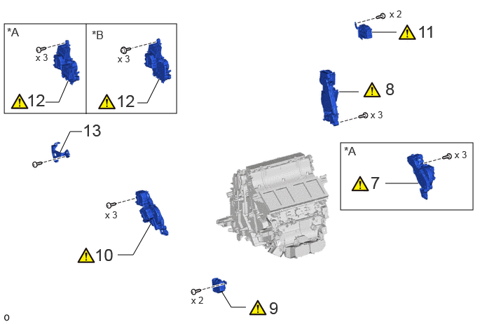
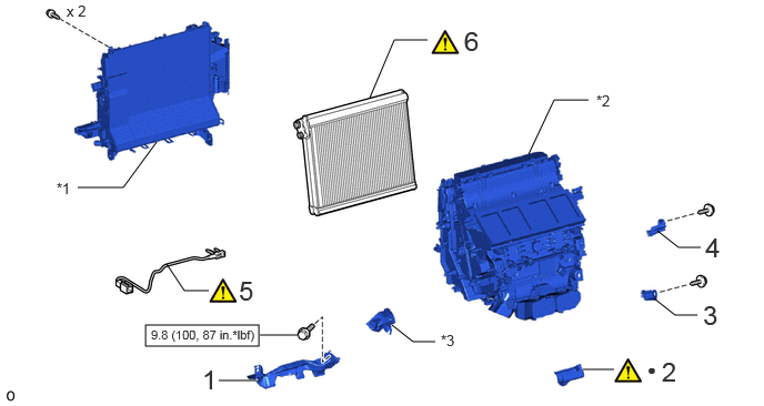
1 NO. 2 AIR DUCT SUB-ASSEMBLY 87201B - - -
2 NO. 1 COOLING UNIT PACKING 88578B (Click here) - -
3 NO. 2 COOLING UNIT BRACKET 88536A - - -
4 NO. 1 COOLING UNIT BRACKET 88536 - - -
5 NO. 1 COOLER THERMISTOR 88625 (Click here) - -
6 NO. 1 COOLER EVAPORATOR SUB-ASSEMBLY 88501 (Click here) - -

*1 HEATER CASE (for Front Side) *2 HEATER CASE (for Rear Side)
*3 NO. 1 AIR DUCT SUB-ASSEMBLY - -
V100146

N*m (kgf*cm, ft.*lbf): Specified torque ● Non-reusable part

E458052N03
5.063,2.125 7.031,3.125 1.969,1 0.063,0.354 2.625,1.688 2.563,1.333 1.75,3.792 1.979,3.792 1.979,3.792 2.24,3.333 false 0.677,1.521 0.875,1.521 0.875,1.521 1.01,1.208 false 2.042,1.531 2.188,1.531 2.188,1.531 2.365,1.177 false 3.292,4.333 3.438,4.573 3.438,4.573 3.656,4.573 false 0.896,2.26 1.042,1.958 1.042,1.958 1.219,1.958 false 1.281,1.698 1.281,0.354 false 5.333,1.365 5.042,1.365 false 5.896,0.479 5.531,0.479 false 5.729,2.729 6.219,2.729 false 0.104,0.375 0.448,0.594 0.344,0.219 12 false *A 5.115,2.146 5.458,2.365 0.344,0.219 12 false *A 1.365,0.417 1.708,0.635 0.344,0.219 12 false *B 0.396,1.344 0.948,1.698 0.552,0.354 18 false 12 1.229,1.792 1.781,2.146 0.552,0.354 18 false 13 1.729,1.354 2.281,1.708 0.552,0.354 18 false 12 6.208,0.323 6.76,0.677 0.552,0.354 18 false 11 1.406,3.646 1.958,4 0.552,0.354 18 false 10 4,4.438 4.552,4.792 0.552,0.354 18 false 9 5.729,1.177 6.281,1.531 0.552,0.354 18 false 8 2.844,4.385 3.156,4.583 0.313,0.198 10 false x 2 1.75,0.792 2.063,0.99 0.313,0.198 10 false x 3 1.563,3.115 1.875,3.313 0.313,0.198 10 false x 3 0.531,0.771 0.844,0.969 0.313,0.198 10 false x 3 5.792,0.125 6.104,0.323 0.313,0.198 10 false x 2 6.76,2.219 7.073,2.417 0.313,0.198 10 false x 3 5.51,1.625 5.823,1.823 0.313,0.198 10 false x 3 5.51,2.573 6.063,2.927 0.552,0.354 18 false 7

Part Name Code Part Name Code
Z101186

Z101188

Z101187

7 NO. 6 AIR CONDITIONING RADIATOR DAMPER SERVO SUB-ASSEMBLY 87050H (Click here) - -
8 NO. 1 AIR CONDITIONING RADIATOR DAMPER SERVO SUB-ASSEMBLY 87050C (Click here) - -
9 NO. 4 AIR CONDITIONING RADIATOR DAMPER SERVO SUB-ASSEMBLY 87050F (Click here) - -
10 NO. 5 AIR CONDITIONING RADIATOR DAMPER SERVO SUB-ASSEMBLY 87050G (Click here) - -
11 NO. 3 AIR CONDITIONING RADIATOR DAMPER SERVO SUB-ASSEMBLY 87050E (Click here) - -
12 NO. 2 AIR CONDITIONING RADIATOR DAMPER SERVO SUB-ASSEMBLY 87050D (Click here) - -
13 NO. 3 COOLING UNIT BRACKET 88536B - - -

*A for 3 Zone Type *B for Dual Type

E458051N05
0.906,0.094 6.271,1.75 5.365,1.656 0.771,3.719 3.115,5.74 2.344,2.021 0.552,3.385 1.583,3.583 1.031,0.198 3.573,0.104 3.573,1.74 false 2.313,1.083 2.021,0.573 2.021,0.573 1.719,0.573 false 3.458,3.167 3.083,3.167 3.083,3.167 2.917,2.833 false 2.573,2.667 2.573,2.26 2.573,2.26 2.75,2.26 false 2.604,3.292 2.604,2.854 false 2.094,2.781 1.875,2.427 1.875,2.427 1.656,2.427 false 1.01,3.073 1.354,3.073 false 3.573,2.344 3.573,2.01 3.573,2.01 3.74,2.01 false 1.521,2.042 1.906,2.042 false 5.677,2.719 6.083,2.719 false 2.177,4.469 1.948,4.469 1.948,4.469 1.833,4.229 false 5.458,1.083 5.021,0.531 5.021,0.531 4.698,0.531 false 4.458,2.375 4.458,2.76 false 5.844,1.948 6.229,1.948 false 0.771,4.698 3.104,4.698 false 2.177,5.51 1.979,5.51 1.979,5.51 1.854,5.198 false 3.198,2.698 3.198,2.031 3.198,2.031 3.031,2.031 false 3.146,2.542 3.146,2.042 false 1.583,3.479 1.75,3.479 false 0.969,0.125 1.344,0.365 0.375,0.24 12 false *A 3.615,0.156 3.99,0.396 0.375,0.24 12 false *B 1.865,3.458 2.177,3.656 0.313,0.198 10 false x 2 4.313,2.76 4.719,3.115 0.406,0.354 18 false 24 1.198,1.917 1.531,2.271 0.333,0.354 18 false 23 6.26,1.792 6.563,2.094 0.302,0.302 18 false 20 2.563,3.25 2.74,3.448 0.177,0.198 10 false ● 2.781,2.156 2.958,2.354 0.177,0.198 10 false ● 2.531,5.323 2.948,5.646 0.417,0.323 18 false 22 6.479,2.552 6.896,2.875 0.417,0.323 18 false 19 1.427,0.417 1.844,0.74 0.417,0.323 18 false 18 4.406,0.406 4.823,0.729 0.417,0.323 18 false 18 0.698,2.938 1.115,3.26 0.417,0.323 18 false 17 1.354,2.26 1.771,2.583 0.417,0.323 18 false 16 3.75,3.042 4.167,3.365 0.417,0.323 18 false 15 4.021,1.885 4.438,2.208 0.417,0.323 18 false 14 2.51,4.313 2.927,4.635 0.417,0.323 18 false 21 0.865,3.76 1.24,4 0.375,0.24 12 false *C 0.865,4.771 1.24,5.01 0.375,0.24 12 false *D 2.917,1.958 3.094,2.156 0.177,0.198 10 false ● 0.646,3.406 1.99,3.625 1.344,0.219 8 false 3.5 (36, 31 in.*lbf)

Procedure Part Name Code
Z101186

Z101188

Z101187

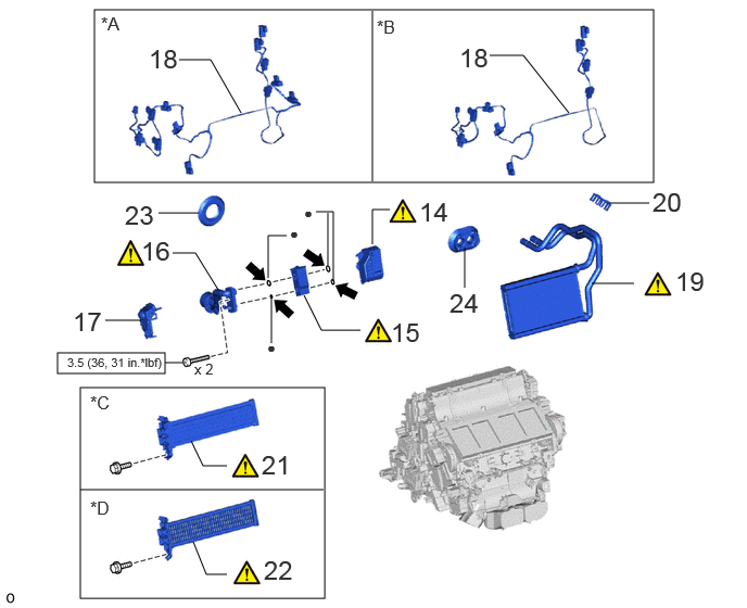
14 NO. 1 COOLER COVER 88891S (Click here) - -
15 COOLER EXPANSION VALVE 88515 (Click here) - -
16 AIR CONDITIONING TUBE AND ACCESSORY ASSEMBLY 88710H (Click here) - -
17 NO. 2 COOLER COVER 88H92 - - -
18 AIR CONDITIONING HARNESS ASSEMBLY 82210K - - -
19 HEATER RADIATOR UNIT SUB-ASSEMBLY 87107B (Click here) - -
20 HEATER CLAMP 87124C - - -
21 QUICK HEATER ASSEMBLY 87710G (Click here) - -
22 HEATER COVER 87114B (Click here) - -
23 COOLING UNIT PARTS 88H99 - - -
24 HEATER GROMMET 87128 - - -

*A for 3 Zone Type *B for Dual Type
*C w/ PTC Heater *D w/o PTC Heater
V100146

N*m (kgf*cm, ft.*lbf): Specified torque ● Non-reusable part
V100135

Compressor oil ND-OIL 11 or equivalent - -

E458059N03
5.771,1.417 5.958,1.729 5.958,1.729 6.292,1.729 false 5.875,5.042 6.323,5.042 false 1.448,3.625 1.885,3.625 false 5.646,3.823 5.333,3.823 5.333,3.823 5.063,3.646 false 3.188,5.375 3.469,5.375 false 2.979,4.563 3.188,4.76 3.188,4.76 3.49,4.76 false 5.177,2.667 5.354,2.833 5.354,2.833 5.573,2.833 false 6.323,1.594 6.677,1.948 0.354,0.354 18 false 31 3.573,4.635 3.958,4.99 0.385,0.354 18 false 30 3.5,5.25 3.948,5.573 0.448,0.323 18 false 29 6.167,3.677 6.531,4.031 0.365,0.354 18 false 28 5.906,2.708 6.292,3.063 0.385,0.354 18 false 27 5.604,4.927 5.99,5.281 0.385,0.354 18 false 26 2.188,3.49 2.563,3.844 0.375,0.354 18 false 25 6.021,3.698 6.177,3.917 0.156,0.219 10 false ●

Procedure Part Name Code
Z101186

Z101188

Z101187

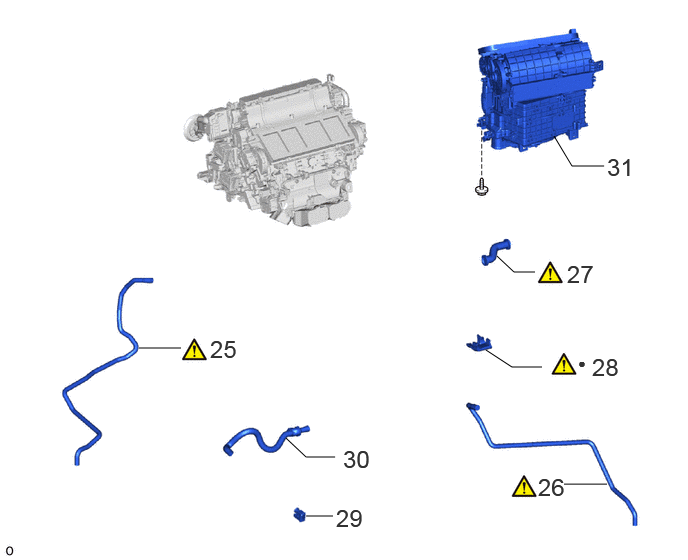
25 NO. 4 COOLER UNIT DRAIN HOSE 88539N (Click here) - -
26 NO. 3 COOLER UNIT DRAIN HOSE 88539E (Click here) - -
27 NO. 1 COOLER UNIT DRAIN HOSE 88539 (Click here) - -
28 NO. 2 COOLING UNIT PACKING 88578C (Click here) - -
29 COOLER THERMISTOR (ROOM TEMPERATURE SENSOR) 88625Q - - -
30 ASPIRATOR 88897P - - -
31 BLOWER ASSEMBLY 87130D - - -

● Non-reusable part - -

PROCEDURE

Hide 87201B 1.INSTALL NO. 2 AIR DUCT SUB-ASSEMBLY

Torque:
9.8 N*m (100 kgf*cm, 87 in.*lbf)

Hide 88578B 2.INSTALL NO. 1 COOLING UNIT PACKING
a.
E456744C01
2.115,0.604 2.688,0.604 true 2.875,0.438 2.875,0.24 2.875,0.24 2.063,0.25 true 1.896,0.156 2.208,0.354 0.313,0.198 10 false *a 1.969,0.531 2.281,0.729 0.313,0.198 10 false *a 0.74,0.146 1.021,0.5 0.281,0.354 18 false i
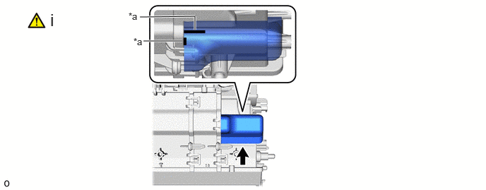
*a Specified Application Position for Packing - -


i.

Install a new No. 1 cooling unit packing in the position shown in the illustration.

NOTICE:

Check that any remaining No. 1 cooling unit packing has been completely removed from the heater case.


Hide 88536A 3.INSTALL NO. 2 COOLING UNIT BRACKET

Hide 88536 4.INSTALL NO. 1 COOLING UNIT BRACKET

Hide 88625 5.INSTALL NO. 1 COOLER THERMISTOR

Z101186

Click here(Click here)

Hide 88501 6.INSTALL NO. 1 COOLER EVAPORATOR SUB-ASSEMBLY
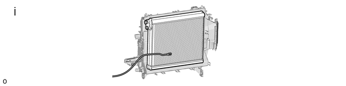
a.
E456740N02
0.281,0.083 0.604,0.479 0.323,0.396 18 false i

i.

Install the No. 1 cooler evaporator sub-assembly to the heater case.
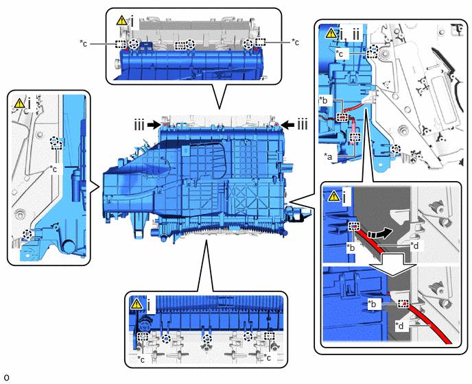


b.
E458056C01
4.021,0.646 4.406,0.646 true 1.365,0.667 1.75,0.667 true 5.302,0.813 5.552,0.813 true 5.365,3.698 5.365,3.49 true 5.771,4.615 6.021,4.615 true 5.729,3.729 6.25,3.729 true 6.219,4.948 6.542,4.948 true 4.094,5.156 4.094,5.354 true 2.167,5.177 2.167,5.375 true 0.854,2.271 0.854,2.49 true 5.115,2.375 5.385,2.375 5.385,2.375 5.385,2.146 true 5.031,1.521 5.198,1.521 5.198,1.521 5.198,1.729 true 1.979,0.167 2.115,0.458 0.135,0.292 18 true i 5.156,0.365 5.51,0.635 0.354,0.271 18 true i, ii 5.198,2.844 5.333,3.135 0.135,0.292 18 true i 2.229,4.479 2.365,4.771 0.135,0.292 18 true i 0.417,1.417 0.552,1.708 0.135,0.292 18 true i 4.917,2.292 5.125,2.469 0.208,0.177 10 true *a 4.844,1.438 5.052,1.615 0.208,0.177 10 true *b 5.583,4.531 5.792,4.708 0.208,0.177 10 true *b 5.26,3.677 5.469,3.854 0.208,0.177 10 true *b 6.229,3.646 6.438,3.823 0.208,0.177 10 true *d 6,4.865 6.208,5.042 0.208,0.177 10 true *d 4,5.344 4.208,5.521 0.208,0.177 10 true *c 2.083,5.375 2.292,5.552 0.208,0.177 10 true *c 0.75,2.479 0.958,2.656 0.208,0.177 10 true *c 1.208,0.573 1.417,0.75 0.208,0.177 10 false *c 4.427,0.552 4.635,0.729 0.208,0.177 10 true *c 2.031,1.74 2.25,2.01 0.219,0.271 18 false iii 4.51,1.729 4.75,2.01 0.24,0.281 18 false iii 5.094,0.729 5.302,0.906 0.208,0.177 10 true *c
*a Clamp *b Guide
*c Guide Pin *d No. 1 Cooler Thermistor Lead Wire
V113147

Secure the Lead Wire between Guide - -


i.

While inserting the No. 1 cooler thermistor into the guide, insert the guide pin and attach the claw as shown in the illustration.


ii.

Attach the clamp.


iii.

Install the heater case with the 2 screws.


Hide 87050H 7.INSTALL NO. 6 AIR CONDITIONING RADIATOR DAMPER SERVO SUB-ASSEMBLY (for 3 Zone Type)
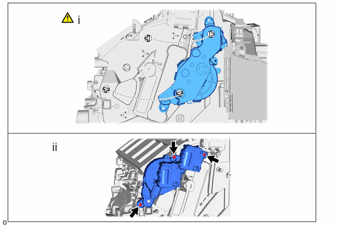
a.
E456746N01
0.167,0.063 6.698,4.708 6.531,4.646 0.177,2.833 6.688,2.833 false 1.646,0.271 1.865,0.552 0.219,0.281 18 false i 1.104,2.969 1.323,3.25 0.219,0.281 18 false ii

i.

Align the direction of the fitting on the heater case to the fitting on the No. 6 air conditioning radiator damper servo sub-assembly as shown in the illustration.


ii.

Install the No. 6 air conditioning radiator damper servo sub-assembly with the 3 screws.


Hide 87050C 8.INSTALL NO. 1 AIR CONDITIONING RADIATOR DAMPER SERVO SUB-ASSEMBLY
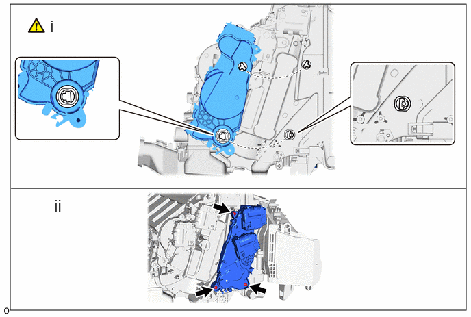
a.
E456747N01
0.156,0.063 7.094,4.719 6.938,4.656 0.167,2.865 7.083,2.865 false 0.76,0.25 1.042,0.604 0.281,0.354 18 false i 0.823,2.979 1.104,3.333 0.281,0.354 18 false ii

i.

Align the direction of the fitting on the heater case to the fitting on the No. 1 air conditioning radiator damper servo sub-assembly as shown in the illustration.


ii.

Install the No. 1 air conditioning radiator damper servo sub-assembly with the 3 screws.


Hide 87050F 9.INSTALL NO. 4 AIR CONDITIONING RADIATOR DAMPER SERVO SUB-ASSEMBLY
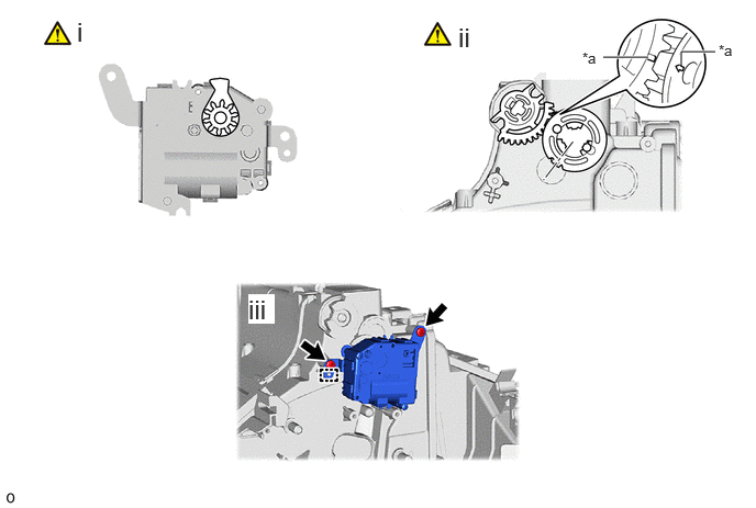
a.
E456745C01
5.719,0.542 6.021,0.542 6.021,0.542 6.146,0.542 true 6.458,0.615 6.458,0.49 6.458,0.49 6.781,0.49 true 5.521,0.469 5.833,0.667 0.313,0.198 10 false *a 6.813,0.396 7.125,0.594 0.313,0.198 10 false *a 0.729,0.156 1.01,0.51 0.281,0.354 18 false i 4.344,0.208 4.625,0.563 0.281,0.354 18 false ii 2.354,2.792 2.604,3.073 0.25,0.281 18 true iii
*a Matchmarks - -


i.

Make sure that the servo motor gear is installed at the position shown.


ii.

Align with the matchmarks on the gear as shown in the illustration.


iii.

Align the guide and install the No. 4 air conditioning radiator damper servo sub-assembly with the 2 screws.


Hide 87050G 10.INSTALL NO. 5 AIR CONDITIONING RADIATOR DAMPER SERVO SUB-ASSEMBLY
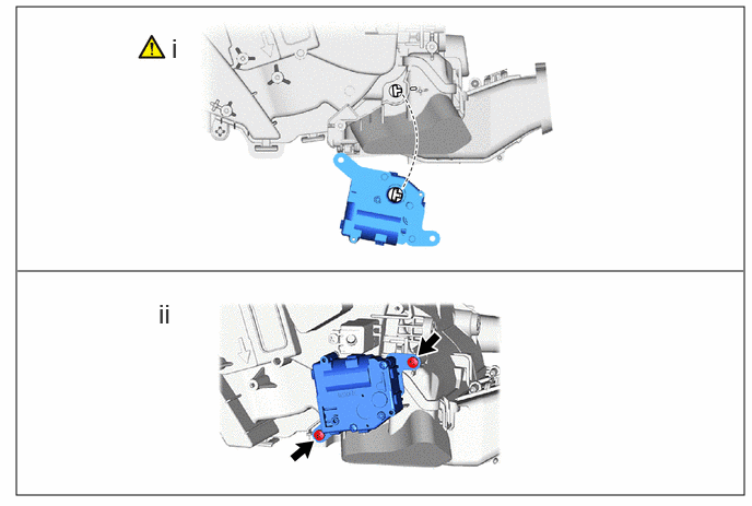
a.
E458058N01
0.156,0.063 7.094,4.719 6.938,4.656 0.167,2.583 7.083,2.583 false 1.635,0.313 1.917,0.667 0.281,0.354 18 false i 1.51,2.844 1.792,3.198 0.281,0.354 18 false ii

i.

Align the direction of the fitting on the heater case to the fitting on the No. 5 air conditioning radiator damper servo sub-assembly as shown in the illustration.


ii.

Install the No. 5 air conditioning radiator damper servo sub-assembly with the 2 screws.


Hide 87050E 11.INSTALL NO. 3 AIR CONDITIONING RADIATOR DAMPER SERVO SUB-ASSEMBLY
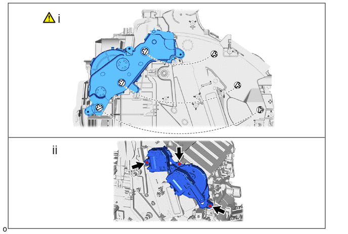
a.
E456748N02
0.167,0.063 6.698,4.708 6.531,4.646 0.177,2.833 6.688,2.833 false 1.188,0.229 1.406,0.51 0.219,0.281 18 false i 1.073,2.938 1.292,3.219 0.219,0.281 18 false ii

i.

Align the direction of the fitting on the heater case to the fitting on the No. 3 air conditioning radiator damper servo sub-assembly as shown in the illustration.


ii.

Install the No. 3 air conditioning radiator damper servo sub-assembly with the 3 screws.


Hide 87050D 12.INSTALL NO. 2 AIR CONDITIONING RADIATOR DAMPER SERVO SUB-ASSEMBLY
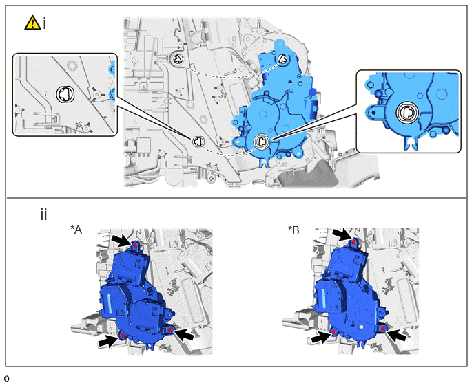
a.
E458054C02
0.083,0.083 7.063,5.552 6.979,5.469 0.104,3 7.052,3 false 1.063,3.375 1.323,3.583 0.26,0.208 12 true *A 4.354,3.385 4.615,3.594 0.26,0.208 12 true *B 0.604,3.094 0.865,3.375 0.26,0.281 18 false ii 0.646,0.198 0.906,0.479 0.26,0.281 18 false i
*A for 3 Zone Type *B for Dual Type


i.

Align the direction of the fitting on the heater case to the fitting on the No. 2 air conditioning radiator damper servo sub-assembly as shown in the illustration.


ii.

Install the No. 2 air conditioning radiator damper servo sub-assembly with the 3 screws.


Hide 88536B 13.INSTALL NO. 3 COOLING UNIT BRACKET

Hide 88891S 14.INSTALL NO. 1 COOLER COVER

a.
E456079C01
1.594,0.135 1.875,0.49 0.281,0.354 18 false i
V113147

Install in this Direction - -


i.

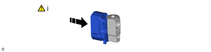
Remove the vinyl tape from the cooler expansion valve and then install the No. 1 cooler cover to the cooler expansion valve.


Hide 88515 15.INSTALL COOLER EXPANSION VALVE
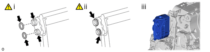
a.
E456749N01
0.458,0.073 0.74,0.427 0.281,0.354 18 false i 2.865,0.073 3.146,0.427 0.281,0.354 18 false ii 4.823,0.073 5.104,0.427 0.281,0.354 18 false iii

i.

Remove the vinyl tape from the No. 1 cooler evaporator sub-assembly and then apply a sufficient amount of compressor oil to 2 new O-rings and the fitting surface with the No. 1 cooler evaporator of the cooler expansion valve.

Compressor Oil:

ND-OIL 11 or equivalent


ii.

Install the 2 O-rings to the No. 1 cooler evaporator sub-assembly.

NOTICE:

Keep the O-rings and O-ring fitting surfaces free of foreign matter.


iii.

Install the cooler expansion valve together with the No. 1 cooler cover.

NOTICE:

Make sure not to cut the O-ring while installing it. (Cut O-rings cannot be installed.)


Hide 88710H 16.INSTALL AIR CONDITIONING TUBE AND ACCESSORY ASSEMBLY
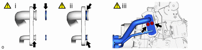
a.
E456750N01
0.521,0.052 0.802,0.406 0.281,0.354 18 false i 2.469,0.052 2.75,0.406 0.281,0.354 18 false ii 4.323,0.052 4.604,0.406 0.281,0.354 18 false iii

i.

Remove the vinyl tape from the air conditioning tube assembly and then apply a sufficient amount of compressor oil to 2 new O-rings and the fitting surface of the cooler expansion valve and air conditioning tube assembly.

Compressor Oil:

ND-OIL 11 or equivalent


ii.

Install the 2 O-rings to the air conditioning tube assembly.

NOTICE:

Keep the O-rings and O-ring fitting surfaces free of foreign matter.


iii.

Using a 4 mm hexagon socket wrench, install the air conditioning accessory assembly with the 2 hexagon bolts.

Torque:
3.5 N*m (36 kgf*cm, 31 in.*lbf)

NOTICE:

Make sure not to cut the O-ring while installing it. (Cut O-rings cannot be installed.)


Hide 88H92 17.INSTALL NO. 2 COOLER COVER

Hide 82210K 18.INSTALL AIR CONDITIONING HARNESS ASSEMBLY

Hide 87107B 19.INSTALL HEATER RADIATOR UNIT SUB-ASSEMBLY

Z101186

NOTICE:

Securely insert the heater radiator unit sub-assembly as far as it will go.


Hide 87124C 20.INSTALL HEATER CLAMP

Hide 87710G 21.INSTALL QUICK HEATER ASSEMBLY (w/ PTC Heater)
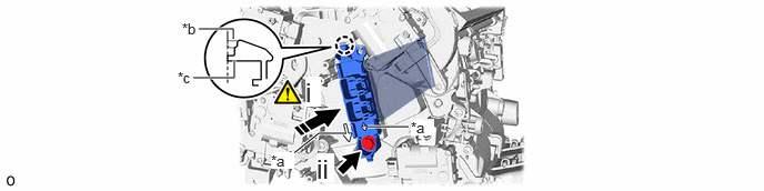
a.
E456751C01
3.448,1.188 3.688,1.188 3.688,1.188 3.833,1.188 true 2.729,1.458 2.99,1.25 2.99,1.25 3.24,1.25 true 1.813,0.729 2.198,0.729 2.198,0.729 2.198,0.563 true 2.188,0.365 2.188,0.271 2.188,0.271 1.865,0.271 true 2.865,0.719 3.01,1 0.146,0.281 18 true i 3.854,1.115 4.073,1.271 0.219,0.156 10 true *a 2.542,1.427 2.76,1.583 0.219,0.156 10 true *a 1.708,0.188 1.927,0.344 0.219,0.156 10 false *b 1.667,0.646 1.885,0.802 0.219,0.156 10 false *c 2.969,1.438 3.135,1.708 0.167,0.271 18 true ii
*a Matchmarks *b Heater Case Fitting Surface
*c Quick Heater Claw - -
V113147

Install in this Direction - -


i.

Align the matchmark on the quick heater assembly with the matchmark on the heater case as shown in the illustration, insert the quick heater assembly into the heater case and attach the claw.

NOTICE:
·
E382588C02
0.677,1.646 0.677,1 true 0.188,1.646 0.188,0.896 0.188,0.896 0.5,0.896 true 0.604,1.667 0.917,1.865 0.313,0.198 10 false *a 0.115,1.667 0.427,1.865 0.313,0.198 10 false *b
*a Element
*b Fin


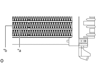
Do not hold the quick heater assembly by the element or fin. Also, do not damage the quick heater assembly.

·

Foul odors may occur due to oil adhering to the quick heater assembly.

·

Check that the heights of the claw fitting surface on the heater case and the claw of the quick heater assembly are aligned.


HINT:
E386232C03
1.885,0.375 2.469,0.375 true 2.51,0.281 2.823,0.479 0.313,0.198 10 false *a
*a Screw Insertion Hole


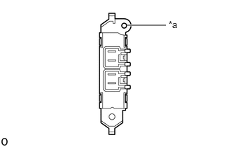
If the claws of the quick heater assembly are damaged, install the quick heater assembly with screw (90159-60431).


ii.

Install the quick heater assembly with the screw.


Hide 87114B 22.INSTALL HEATER COVER (w/o PTC Heater)

a.

Use the same procedure as for the quick heater assembly.


Hide 88H99 23.INSTALL COOLING UNIT PARTS

Hide 87128 24.INSTALL HEATER GROMMET

Hide 88539N 25.INSTALL NO. 4 COOLER UNIT DRAIN HOSE
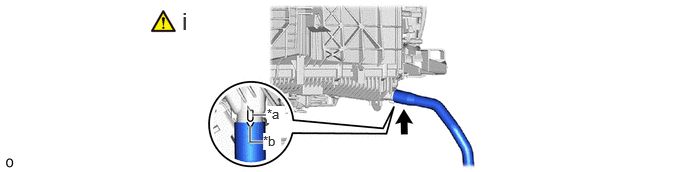
a.
E456753C01
2.74,1.479 2.604,1.479 2.604,1.479 2.604,1.313 true 2.625,1.198 2.771,1.198 true 2.781,1.104 2.969,1.281 0.188,0.177 10 true *a 2.74,1.385 2.927,1.563 0.188,0.177 10 true *b 1.896,0.073 2.177,0.427 0.281,0.354 18 false i
*a Protrusion *b Cutout


i.

Align the cutout of the No. 4 cooler unit drain hose with the protrusion of the heater case and install the No. 4 cooler unit drain hose.


Hide 88539E 26.INSTALL NO. 3 COOLER UNIT DRAIN HOSE
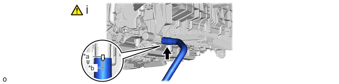
a.
E456754C01
2.177,1.302 2.177,1.448 2.177,1.448 2.042,1.448 true 1.969,1.208 2.146,1.208 true 1.813,0.052 2.094,0.406 0.281,0.354 18 false i 1.76,1.115 1.958,1.281 0.198,0.167 10 true *a 1.865,1.365 2.063,1.531 0.198,0.167 10 true *b
*a Protrusion *b Cutout


i.

Align the cutout of the No. 3 cooler unit drain hose with the protrusion of the heater case and install the No. 3 cooler unit drain hose.

NOTICE:

Check that any remaining No. 1 cooling unit packing has been completely removed from the heater case, No. 3 cooler unit drain hose.


Hide 88539 27.INSTALL NO. 1 COOLER UNIT DRAIN HOSE

Z101186

NOTICE:

Check that any remaining No. 1 cooling unit packing has been completely removed from the No. 1 cooler unit drain hose.


Hide 88578C 28.INSTALL NO. 2 COOLING UNIT PACKING
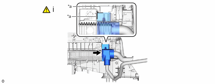
a.
E456755C01
2.396,0.552 3.219,0.552 true 3.333,0.396 3.333,0.219 3.333,0.219 2.427,0.219 true 2.26,0.125 2.573,0.323 0.313,0.198 10 false *a 2.24,0.458 2.552,0.656 0.313,0.198 10 false *a 1.75,0.156 1.885,0.469 0.135,0.313 18 false i
*a Specified Application Position for Packing - -


i.

Install a new No. 2 cooling unit packing in the position shown in the illustration.

NOTICE:

Check that any remaining No. 2 cooling unit packing has been completely removed from the heater case, No. 1 cooler unit drain hose and No. 3 cooler unit drain hose.


Hide 88625Q 29.INSTALL COOLER THERMISTOR (ROOM TEMPERATURE SENSOR)

Hide 88897P 30.INSTALL ASPIRATOR

Hide 87130D 31.INSTALL BLOWER ASSEMBLY