HEATING / AIR CONDITIONING HEATER WATER PUMP INSTALLATION
CAUTION / NOTICE / HINT
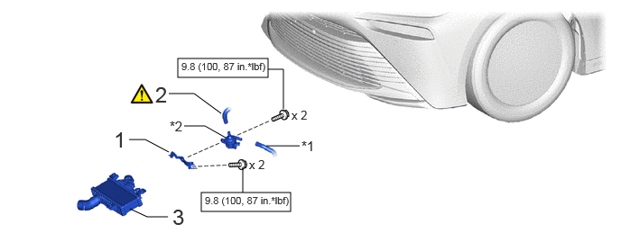
| Procedure | Part Name Code | 
|

|

|
|
|---|---|---|---|---|---|
| 1 | WATER PUMP BRACKET | 87121W | - | - | - |
| 2 | WATER PUMP ASSEMBLY WITH MOTOR | G9040D | ( ) |
- | - |
| 3 | INTERCOOLER ASSEMBLY WITH SENSOR | 17900 | - | - | |
| *1 | WATER HOSE SUB-ASSEMBLY | *2 | HEATER ACCESSORY ASSEMBLY |

|
N*m (kgf*cm, ft.*lbf): Specified torque | - | - |
PROCEDURE

 87121W
1.INSTALL WATER PUMP BRACKET
- Torque:
- 9.8 N*m (100 kgf*cm, 87 in.*lbf)
G9040D
2.INSTALL WATER PUMP ASSEMBLY WITH MOTOR
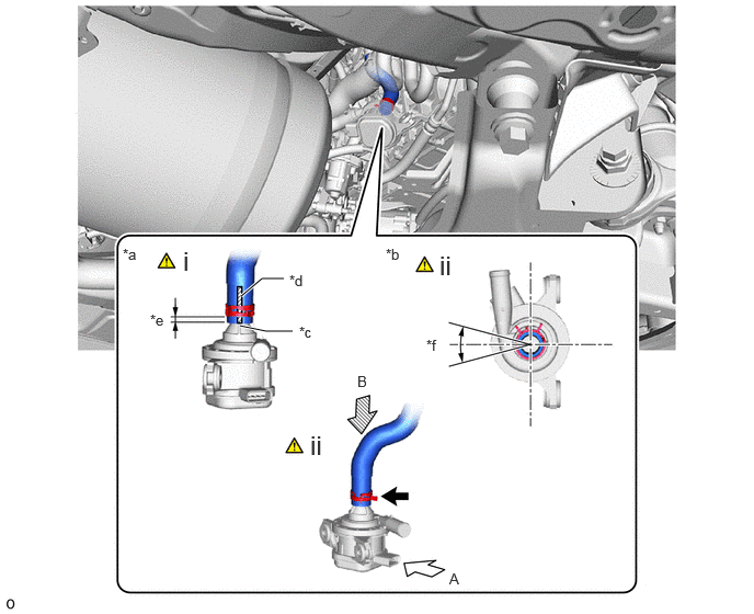
| *a | View A | *b | View B |
| *c | Positioning Rib | *d | Marking (White) |
| *e | Hose Clip Installation Range 3 to 7 mm (0.118 to 0.276 in.)) | *f | Hose Clip Installation Angle (30°) |
Align the marking of the heater accessory assembly with the positioning rib of the water pump with motor assembly and connect the heater accessory assembly.
- NOTICE:
-
Do not apply excessive force to the heater accessory assembly.
Install the hose clip within the range shown in the illustration.
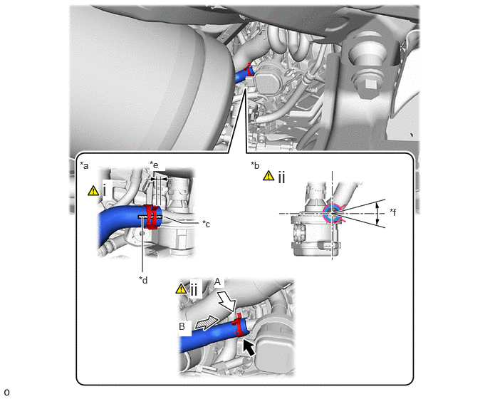
| *a | View A | *b | View B |
| *c | Positioning Rib | *d | Marking (White) |
| *e | Hose Clip Installation Range 3 to 7 mm (0.118 to 0.276 in.)) | *f | Hose Clip Installation Angle (30°) |
Align the marking of the water hose with the positioning rib of the water pump with motor assembly and connect the heater accessory assembly.
- NOTICE:
-
Do not apply excessive force to the water hose sub-assembly.
Install the hose clip within the range shown in the illustration.
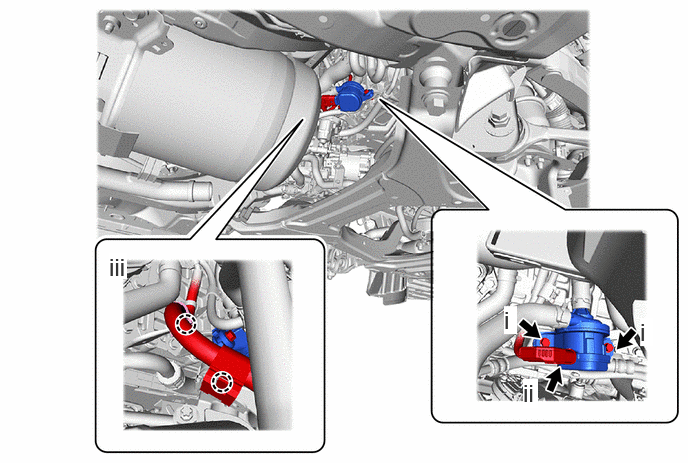
Install the water pump assembly with motor with the 2 bolts.
- Torque:
- 9.8 N*m (100 kgf*cm, 87 in.*lbf)
Connect the connector.
Attach the claw to connect the wire harness.
17900
3.INSTALL INTERCOOLER ASSEMBLY WITH SENSOR