STEERING COLUMN POWER TILT AND POWER TELESCOPIC STEERING COLUMN SYSTEM B261096 Tilt Position Sensor or Tilt Motor Circuit Component Internal Failure
DESCRIPTION
The tilt motor (steering column assembly) is operated by the power source voltage supplied from the multiplex tilt and telescopic ECU and tilts the steering column up and down. The tilt position sensor (Hall IC) in the tilt motor (steering column assembly) detects the tilt angle of the steering column assembly and sends a signal to the multiplex tilt and telescopic ECU based on that angle.
| DTC No. | Detection Item | DTC Detection Condition | Trouble Area | DTC Output from | Priority |
|---|---|---|---|---|---|
| B261096 | Tilt Position Sensor or Tilt Motor Circuit Component Internal Failure | Tilt operation stops within the operation range while operating. | ·
TI&TE Fuse ·
Tilt position sensor (steering column assembly) ·
Tilt motor (steering column assembly) ·
Harness or connector ·
Multiplex tilt and telescopic ECU |
Tilt&Telescopic | A |
WIRING DIAGRAM
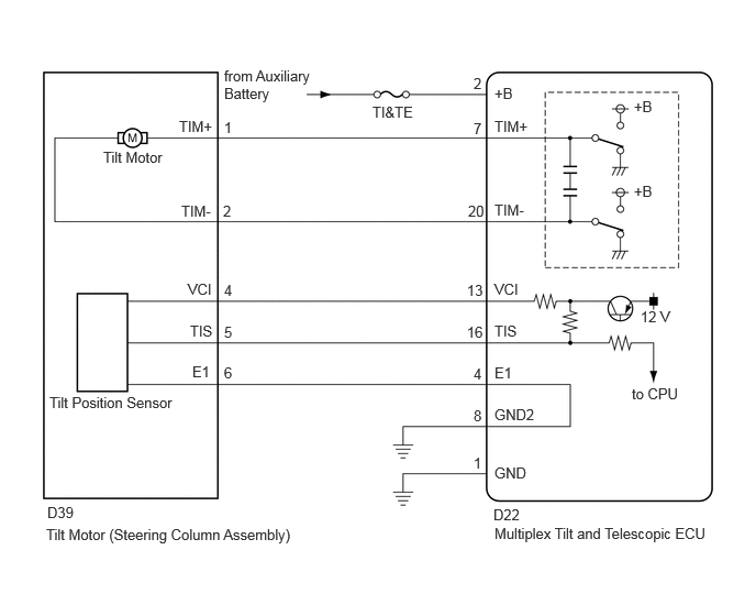
CAUTION / NOTICE / HINT
- NOTICE:
-
Inspect the fuses for circuits related to this system before performing the following procedure.
PROCEDURE
Check that the steering wheel tilts up and down.
- Body Electrical > Tilt&Telescopic > Active Test
-
Tester Display Tilt Motor - 50004 406 42000
- Body Electrical > Tilt&Telescopic > Active Test
-
Tester Display Measurement Item Control Range Tilt Motor Tilt operation UP/DOWN
- OK:
The steering wheel tilts up and down.
- Result:
Proceed to OK NG
OK
NG
Pre-procedure1
Disconnect the D22 multiplex tilt and telescopic ECU connector.
Disconnect the D39 tilt motor (steering column assembly) connector.
Procedure1
Measure the resistance according to the value(s) in the table below.
- Standard Resistance:
Tester Connection Condition Specified Condition Click Location & Routing(D22,D39)Location & Routingewd_type=routing;type=c,c;code=D22,D39
Click Connector(D22)Instrument Panel>Instrument Panel Wire>Multiplex Tilt & Telescopic ECUewd_type=component;type=c;code=D22;pinno=13,16,4
Click Connector(D39)Instrument Panel>Instrument Panel Wire>Steering Column Assemblyewd_type=component;type=c;code=D39;pinno=4,5,6
D22-13 (VCI) - D39-4 (VCI) Always Below 1 Ω D22-16 (TIS) - D39-5 (TIS) Always Below 1 Ω D22-4 (E1) -D39-6 (E1) Always Below 1 Ω D22-13 (VCI) or D39-4 (VCI) - Body ground Always 10 kΩ or higher D22-16 (TIS) or D39-5 (TIS) - Body ground Always 10 kΩ or higher D22-4 (E1) or D39-6 (E1) - Body ground Always 10 kΩ or higher
- Result:
Proceed to OK NG
Post-procedure1
None
OK
NG
Pre-procedure1
Disconnect the D22 multiplex tilt and telescopic ECU connector.
Procedure1
Measure the resistance according to the value(s) in the table below.
- Standard Resistance:
Tester Connection Condition Specified Condition Click Location & Routing(D22)Location & Routingewd_type=routing;type=c;code=D22
Click Connector(D22)Instrument Panel>Instrument Panel Wire>Multiplex Tilt & Telescopic ECUewd_type=component;type=c;code=D22;pinno=1,8
D22-1 (GND) - Body ground Always Below 1 Ω D22-8 (GND2) - Body ground Always Below 1 Ω
- Result:
Proceed to OK NG
Post-procedure1
None
OK
NG
Pre-procedure1
Reconnect the D22 multiplex tilt and telescopic ECU connector.
Disconnect the D39 tilt motor (steering column assembly) connector.
Procedure1
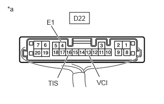
| *a | Component with harness connected
(Multiplex Tilt and Telescopic ECU) |
Measure the voltage according to the value(s) in the table below.
- Standard Voltage:
Tester Connection Condition Specified Condition Click Location & Routing(D22)Location & Routingewd_type=routing;type=c;code=D22
Click Connector(D22)Instrument Panel>Instrument Panel Wire>Multiplex Tilt & Telescopic ECUewd_type=component;type=c;code=D22;pinno=13,4,16
D22-13 (VCI) - D22-4 (E1) Ignition switch ON 8 to 14 V D22-16 (TIS) - D22-4 (E1) Ignition switch ON 8 to 14 V
- Result:
Proceed to OK NG
Post-procedure1
None
OK
NG
Pre-procedure1
Reconnect the D22 multiplex tilt and telescopic ECU connector.
Reconnect the D39 tilt motor (steering column assembly) connector.
Procedure1
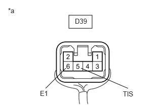
| *a | Component with harness connected
(Tilt Motor (Steering Column Assembly)) |
Measure the voltage according to the value(s) in the table below.
- Standard Voltage:
Tester Connection Condition Specified Condition Click Location & Routing(D39)Location & Routingewd_type=routing;type=c;code=D39
Click Connector(D39)Instrument Panel>Instrument Panel Wire>Steering Column Assemblyewd_type=component;type=c;code=D39;pinno=5,6
D39-5 (TIS) - D39-6 (E1) Steering wheel tilting up or tilting down Pulse generation
High: 8 to 14 V
Low: Below 1 V
- Result:
Proceed to OK NG
Post-procedure1
None
OK
NG
Pre-procedure1
Disconnect the D22 multiplex tilt and telescopic ECU connector.
Procedure1
Measure the voltage according to the value(s) in the table below.
- Standard Voltage:
Tester Connection Condition Specified Condition Click Location & Routing(D22)Location & Routingewd_type=routing;type=c;code=D22
Click Connector(D22)Instrument Panel>Instrument Panel Wire>Multiplex Tilt & Telescopic ECUewd_type=component;type=c;code=D22;pinno=2
D22-2 (+B) - Body ground Ignition switch off 11 to 14 V
- Result:
Proceed to OK NG
Post-procedure1
None
OK
NG
Pre-procedure1
Disconnect the D22 multiplex tilt and telescopic ECU connector.
Procedure1
Measure the resistance according to the value(s) in the table below.
- Standard Resistance:
Tester Connection Condition Specified Condition Click Location & Routing(D22)Location & Routingewd_type=routing;type=c;code=D22
Click Connector(D22)Instrument Panel>Instrument Panel Wire>Multiplex Tilt & Telescopic ECUewd_type=component;type=c;code=D22;pinno=1,8
D22-1 (GND) - Body ground Always Below 1 Ω D22-8 (GND2) - Body ground Always Below 1 Ω
- Result:
Proceed to OK NG
Post-procedure1
None
OK
NG
Pre-procedure1
Disconnect the D22 multiplex tilt and telescopic ECU connector.
Disconnect the D39 tilt motor (steering column assembly) connector.
Procedure1
Measure the resistance according to the value(s) in the table below.
- Standard Resistance:
Tester Connection Condition Specified Condition Click Location & Routing(D22,D39)Location & Routingewd_type=routing;type=c,c;code=D22,D39
Click Connector(D22)Instrument Panel>Instrument Panel Wire>Multiplex Tilt & Telescopic ECUewd_type=component;type=c;code=D22;pinno=7,20
Click Connector(D39)Instrument Panel>Instrument Panel Wire>Steering Column Assemblyewd_type=component;type=c;code=D39;pinno=1,2
D22-7 (TIM+) - D39-1 (TIM+) Always Below 1 Ω D22-20 (TIM-) - D39-2 (TIM-) Always Below 1 Ω D22-7 (TIM+) or D39-1 (TIM+) - Body ground Always 10 kΩ or higher D22-20 (TIM-) or D39-2 (TIM-) - Body ground Always 10 kΩ or higher
- Result:
Proceed to OK NG
Post-procedure1
None
OK
NG
- Result:
Proceed to OK NG
OK
NG