POWER ASSIST SYSTEMS POWER STEERING SYSTEM C155B16 Power Steering Motor "B" Supply Voltage Circuit Voltage Below Threshold C155B17 Power Steering Motor "B" Supply Voltage Circuit Voltage Above Threshold
DESCRIPTION
| DTC No. | Detection Item | DTC Detection Condition | Trouble Area | Warning Indicate | DTC Output from | Priority |
|---|---|---|---|---|---|---|
| C155B16 | Power Steering Motor "B" Supply Voltage Circuit Voltage Below Threshold | PIG voltage of system 2 is at or lower than the specified value | ·
Harness or connector ·
Rack and pinion power steering gear assembly |
EPS warning light: Comes on | EMPS | A |
| C155B17 | Power Steering Motor "B" Supply Voltage Circuit Voltage Above Threshold | PIG voltage of system 2 is at or higher than the specified value | ·
Harness or connector ·
Rack and pinion power steering gear assembly |
EPS warning light: Comes on | EMPS | A |
WIRING DIAGRAM
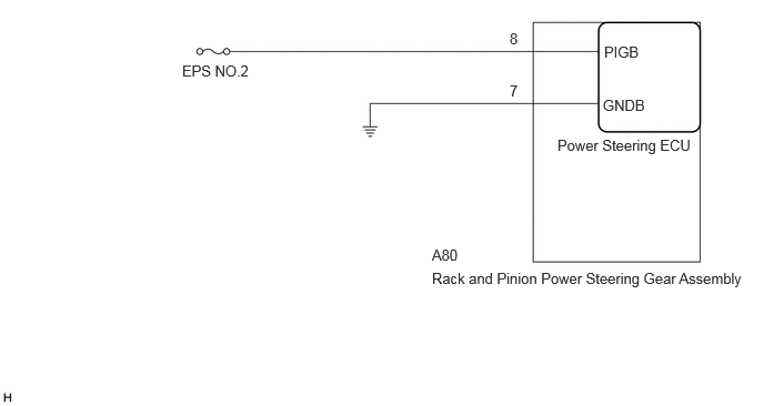
CAUTION / NOTICE / HINT
- NOTICE:
- ·
Inspect the fuses for circuits related to this system before performing the following procedure.
·When replacing the rack and pinion power steering gear assembly, perform Power Steering ECU Initial Setting.
Click hereSteering>POWER ASSIST SYSTEMS>POWER STEERING SYSTEM>UTILITY
PROCEDURE
Pre-procedure1
Disconnect the A80 rack and pinion power steering gear assembly connector.
Procedure1
Measure the resistance according to the value(s) in the table below.
- Standard Resistance:
Tester Connection Condition Specified Condition Click Location & Routing(A80)Location & Routingewd_type=routing;type=c;code=A80
A80-7 (GNDB) - Body ground Always Below 1 Ω
- Result:
Proceed to OK NG
Post-procedure1
None
OK
NG
Pre-procedure1
Disconnect the A80 rack and pinion power steering gear assembly connector.
Procedure1
Measure the voltage according to the value(s) in the table below.
- Standard Voltage:
Tester Connection Condition Specified Condition Click Location & Routing(A80)Location & Routingewd_type=routing;type=c;code=A80
A80-8 (PIGB) - Body ground Always 9 to 16 V
- Result:
Proceed to OK NG
Post-procedure1
None
OK
NG