HEATING / AIR CONDITIONING AIR CONDITIONING SYSTEM B1423 Pressure Sensor Circuit
DESCRIPTION
This DTC is stored if refrigerant pressure on the high pressure side is extremely low (0.176 MPaG (1.8 kgf/cm2, 26 psi) or less) or extremely high (3.025 MPaG (30.8 kgf/cm2, 439 psi) or more). The air conditioner pressure sensor, which is installed to the high pressure side pipe to detect refrigerant pressure, sends a refrigerant pressure signal to the air conditioning amplifier assembly. The air conditioning amplifier assembly converts this signal to a pressure value according to the sensor characteristics and uses it to control the compressor.
| DTC No. | Detection Item | DTC Detection Condition | Trouble Area | Memory | DTC Output from | Priority |
|---|---|---|---|---|---|---|
| B1423 | Pressure Sensor Circuit | ·
Diagnosis condition: Ignition switch ON ·
Malfunction Status: Refrigerant pressure signal malfunction ·
Detection time: Continuously for 4 seconds or more (Present malfunction) |
·
Air conditioner pressure sensor ·
Harness or connector ·
Air conditioning amplifier assembly ·
Cooler expansion valve (blocked, stuck) ·
Cooler condenser assembly (blocked, deterioration of cooling capacity due to dirt) ·
Cooler dryer (moisture in the refrigerant cycle cannot be absorbed) ·
Cooling fan system (cooler condenser assembly cannot be cooled down) ·
Air conditioning system (leaks, blocked) ·
Refrigerant volume (excessive, low) |
- | Air Conditioner | B |
WIRING DIAGRAM
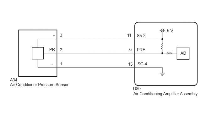
CAUTION / NOTICE / HINT
- NOTICE:
- ·
Be sure to check the refrigerant volume first when this DTC is output because this DTC can also be stored if there is no refrigerant in the cycle.
for HFC-134a (R134a): Click hereVehicle Interior>HEATING / AIR CONDITIONING>REFRIGERANT (for HFC-134a(R134a))>REPLACEMENT
for HFO-1234yf (R1234yf): Click hereVehicle Interior>HEATING / AIR CONDITIONING>REFRIGERANT (for HFO-1234yf(R1234yf))>REPLACEMENT
·If DTC B1423 and B14B8 are output at the same time, troubleshoot for DTC B14B8 first.
Click hereVehicle Interior>HEATING / AIR CONDITIONING>AIR CONDITIONING SYSTEM>B14B8
- HINT:
-
Make sure that the connector is properly connected. If it is not, securely connect it and check for DTCs again.
PROCEDURE
Check for DTCs.
- Body Electrical > Air Conditioner > Trouble Codes
- 50001 121
- Result:
Result Proceed to B1423 and B14B8 are output A B1423 is not output B
A
B
Pre-procedure1
Read the Data List according to the display on the GTS.
- Body Electrical > Air Conditioner > Data List
-
Tester Display Measurement Item Range Normal Condition Diagnostic Note Regulator Pressure Sensor Air conditioner pressure sensor Min.: -0.4566 MPaG
Max.: 3.2943 MPaGActual refrigerant pressure displayed -
- Body Electrical > Air Conditioner > Data List
-
Tester Display Regulator Pressure Sensor - 50003 121 52
Install a manifold gauge set.
- HINT:
-
for HFC-134a (R134a): Click hereVehicle Interior>HEATING / AIR CONDITIONING>REFRIGERANT (for HFC-134a(R134a))>ON-VEHICLE INSPECTION
-
for HFO-1234yf (R1234yf): Click hereVehicle Interior>HEATING / AIR CONDITIONING>REFRIGERANT (for HFO-1234yf(R1234yf))>ON-VEHICLE INSPECTION
Procedure1
Compare the values displayed in the Data List and on the manifold gauge set.
- Result:
Result Proceed to Data List value and manifold gauge set value do not match and Data List value: 0.176 MPaG (1.8 kgf/cm2, 26 psi) or less A Data List value and manifold gauge set value do not match and Data List value: 3.025 MPaG (30.8 kgf/cm2, 439 psi) or more B Data List value matches manifold gauge set value C
Post-procedure1
None
A
B
C
for HFC-134a (R134a): Click hereVehicle Interior>HEATING / AIR CONDITIONING>REFRIGERANT (for HFC-134a(R134a))>ON-VEHICLE INSPECTION
for HFO-1234yf (R1234yf): Click hereVehicle Interior>HEATING / AIR CONDITIONING>REFRIGERANT (for HFO-1234yf(R1234yf))>ON-VEHICLE INSPECTION
Read the Data List according to the display on the GTS.
- Body Electrical > Air Conditioner > Data List
-
Tester Display Measurement Item Range Normal Condition Diagnostic Note Regulator Pressure Sensor Air conditioner pressure sensor Min.: -0.4566 MPaG
Max.: 3.2943 MPaGActual refrigerant pressure displayed -
- Body Electrical > Air Conditioner > Data List
-
Tester Display Regulator Pressure Sensor - 50003 121 52
- OK:
Disconnecting the A39 connector of the air conditioner pressure sensor causes the Data List value to change.
- Result:
Result Proceed to Regulator pressure sensor value changes A Regulator pressure sensor value does not change B
A
B
Pre-procedure1
Disconnect the A34 air conditioner pressure sensor connector.
Procedure1
Measure the voltage according to the value(s) in the table below.
- Standard Voltage:
Tester Connection Switch Condition Specified Condition Click Location & Routing(A34)Location & Routingewd_type=routing;type=c;code=A34
A34-3 (+) - Body ground Ignition switch ON 4.75 to 5.25 V
- Result:
Proceed to OK NG
Post-procedure1
None
OK
NG
Pre-procedure1
Disconnect the A34 air conditioner pressure sensor connector.
Disconnect the D80 air conditioning amplifier assembly connector.
Procedure1
Measure the resistance according to the value(s) in the table below.
- Standard Resistance:
Tester Connection Condition Specified Condition Click Location & Routing(A34,D80)Location & Routingewd_type=routing;type=c,c;code=A34,D80
Click Connector(D80)Instrument Panel>Instrument Panel Wire>Air Conditioning Amplifier Assemblyewd_type=component;type=c;code=D80;pinno=11
A34-3 (+) - D80-11 (S 5-3) Always Below 1 Ω
- Result:
Proceed to OK NG
Post-procedure1
None
OK
NG
Pre-procedure1
Disconnect the A34 air conditioner pressure sensor connector.
Procedure1
Measure the voltage according to the value(s) in the table below.
- Standard Voltage:
Tester Connection Switch Condition Specified Condition Click Location & Routing(A34)Location & Routingewd_type=routing;type=c;code=A34
A34-2 (PR) - Body ground Ignition switch ON 3.0 to 5.25 V
- Result:
Proceed to OK NG
Post-procedure1
None
OK
NG
Pre-procedure1
Disconnect the A34 air conditioner pressure sensor connector.
Disconnect the D80 air conditioning amplifier assembly connector.
Procedure1
Measure the resistance according to the value(s) in the table below.
- Standard Resistance:
Tester Connection Condition Specified Condition Click Location & Routing(A34,D80)Location & Routingewd_type=routing;type=c,c;code=A34,D80
Click Connector(D80)Instrument Panel>Instrument Panel Wire>Air Conditioning Amplifier Assemblyewd_type=component;type=c;code=D80;pinno=6
A34-2 (PR) or D80-6 (PRE) - Other terminals and body ground Always 10 kΩ or higher
- Result:
Proceed to OK NG
Post-procedure1
None
OK
NG
Pre-procedure1
Disconnect the A34 air conditioner pressure sensor connector.
Procedure1
Measure the resistance according to the value(s) in the table below.
- Standard Resistance:
Tester Connection Condition Specified Condition Click Location & Routing(A34)Location & Routingewd_type=routing;type=c;code=A34
A34-1 (-) - Body ground Always Below 1 Ω
- Result:
Proceed to OK NG
Post-procedure1
None
OK
NG
Pre-procedure1
Disconnect the A34 air conditioner pressure sensor connector.
Procedure1
Measure the voltage according to the value(s) in the table below.
- Standard Voltage:
Tester Connection Switch Condition Specified Condition Click Location & Routing(A34)Location & Routingewd_type=routing;type=c;code=A34
A34-2 (PR) - Body ground Ignition switch ON 3.0 to 5.25 V
- Result:
Result Proceed to 5.25 V or higher A 3.0 to 5.25 V B Below 3.0 V C
Post-procedure1
None
A
B
C
Pre-procedure1
Disconnect the A34 air conditioner pressure sensor connector.
Disconnect the D80 air conditioning amplifier assembly connector.
Procedure1
Measure the resistance according to the value(s) in the table below.
- Standard Resistance:
Tester Connection Condition Specified Condition Click Location & Routing(A34,D80)Location & Routingewd_type=routing;type=c,c;code=A34,D80
Click Connector(D80)Instrument Panel>Instrument Panel Wire>Air Conditioning Amplifier Assemblyewd_type=component;type=c;code=D80;pinno=6
A34-2 (PR) or D80-6 (PRE) - Other terminals and body ground Always 10 kΩ or higher
- Result:
Proceed to OK NG
Post-procedure1
None
OK
NG
Pre-procedure1
Disconnect the A34 air conditioner pressure sensor connector.
Procedure1
Measure the resistance according to the value(s) in the table below.
- Standard Resistance:
Tester Connection Switch Condition Specified Condition Click Location & Routing(A34)Location & Routingewd_type=routing;type=c;code=A34
A34-3 (+) - A34-2 (PR) Ignition switch ON 180 to 220 kΩ
- HINT:
-
After turning the ignition switch off, wait at least 30 seconds before performing the measurement.
- Result:
Proceed to OK NG
Post-procedure1
None
OK
NG
Pre-procedure1
Disconnect the A39 air conditioner pressure sensor connector.
Disconnect the G64 air conditioning amplifier assembly connector.
Procedure1
Measure the resistance according to the value(s) in the table below.
- Standard Resistance:
Tester Connection Condition Specified Condition Click Location & Routing(A34,D80)Location & Routingewd_type=routing;type=c,c;code=A34,D80
Click Connector(D80)Instrument Panel>Instrument Panel Wire>Air Conditioning Amplifier Assemblyewd_type=component;type=c;code=D80;pinno=6,11
A34-2 (PR) or D80-6 (PRE) - Other terminals and body ground Always 10 kΩ or higher A34-3 (+) or D80-11 (S 5-3) - Other terminals and body ground Always 10 kΩ or higher
- Result:
Proceed to OK NG
Post-procedure1
None
OK
NG
Pre-procedure1
Disconnect the A34 air conditioner pressure sensor connector.
Disconnect the D80 air conditioning amplifier assembly connector.
Procedure1
Measure the resistance according to the value(s) in the table below.
- Standard Resistance:
Tester Connection Condition Specified Condition Click Location & Routing(A34,D80)Location & Routingewd_type=routing;type=c,c;code=A34,D80
Click Connector(D80)Instrument Panel>Instrument Panel Wire>Air Conditioning Amplifier Assemblyewd_type=component;type=c;code=D80;pinno=6
A34-2 (PR) - D80-6 (PRE) Always Below 1 Ω
- Result:
Proceed to OK NG
Post-procedure1
None
OK
NG
Pre-procedure1
Disconnect the A34 air conditioner pressure sensor connector.
Disconnect the D80 air conditioning amplifier assembly connector.
Procedure1
Measure the resistance according to the value(s) in the table below.
- Standard Resistance:
Tester Connection Condition Specified Condition Click Location & Routing(A34,D80)Location & Routingewd_type=routing;type=c,c;code=A34,D80
Click Connector(D80)Instrument Panel>Instrument Panel Wire>Air Conditioning Amplifier Assemblyewd_type=component;type=c;code=D80;pinno=15
A34-1 (-) - D80-15 (SG-4) Always Below 1 Ω
- Result:
Proceed to OK NG
Post-procedure1
None
OK
NG