METER / GAUGE / DISPLAY HEADUP DISPLAY SYSTEM Main Switch Circuit
DESCRIPTION
The trip switch (headup display switch) and meter mirror sub-assembly are connected via direct line. The meter mirror sub-assembly can be turned off and on by operating the trip switch (headup display switch).
WIRING DIAGRAM
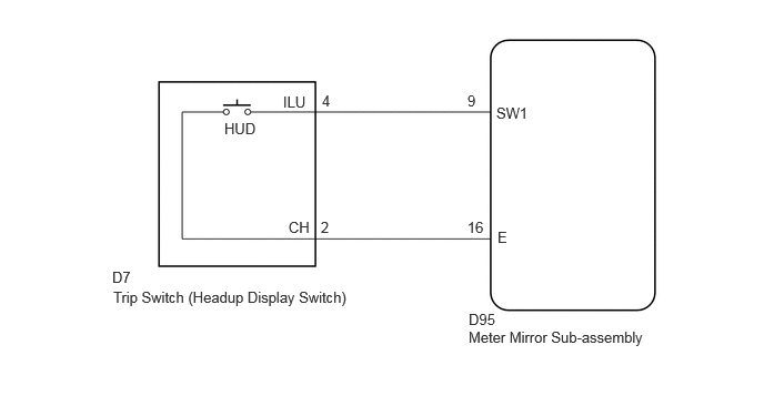
PROCEDURE
Read the Data List according to the display on the GTS.
- Body Electrical > Head Up Display > Data List
-
Tester Display Measurement Item Range Normal Condition Diagnostic Note Main Switch Trip switch (headup display switch) status OFF or ON OFF: Switch released
ON: Switch pushed-
- Body Electrical > Head Up Display > Data List
-
Tester Display Main Switch - 50003 408 2
- OK:
Trip switch (headup display switch) condition displayed on the GTS changes with the actual switch operation.
- Result:
Proceed to OK NG
OK
NG
Click hereVehicle Interior>METER / GAUGE / DISPLAY>HEADUP DISPLAY SWITCH>INSPECTION
- Result:
Proceed to OK NG
OK
NG
Disconnect the D95 meter mirror sub-assembly connector.
Disconnect the D7 trip switch (headup display switch) connector.
Measure the resistance according to the value(s) in the table below.
- Standard Resistance:
Tester Connection Condition Specified Condition Click Location & Routing(D95,D7)Location & Routingewd_type=routing;type=c,c;code=D95,D7
Click Connector(D95)Instrument Panel>Instrument Panel Wire>Meter Mirror Sub-Assemblyewd_type=component;type=c;code=D95;pinno=9,16
Click Connector(D7)Instrument Panel>Instrument Panel Wire>Trip Switchewd_type=component;type=c;code=D7;pinno=4,2
D95-9 (SW1) - D7-4 (ILU) Always Below 1 Ω D95-16 (E) - D7-2 (CH) Always Below 1 Ω D95-9 (SW1) or D7-4 (ILU) - Body ground Always 10 kΩ or higher D95-16 (E) or D7-2 (CH) - Body ground Always 10 kΩ or higher
- Result:
Proceed to OK NG
OK
NG