WIPER / WASHER FRONT WIPER MOTOR INSTALLATION
CAUTION / NOTICE / HINT
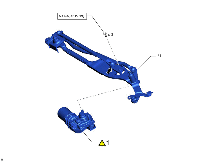
| Procedure | Part Name Code | 
|

|

|
|
|---|---|---|---|---|---|
| 1 | WINDSHIELD WIPER MOTOR ASSEMBLY | 85110 | ( ) |
- | - |
| *1 | FRONT WIPER LINK | - | - |

|
N*m (kgf*cm, ft.*lbf): Specified torque | 
|
MP Grease |
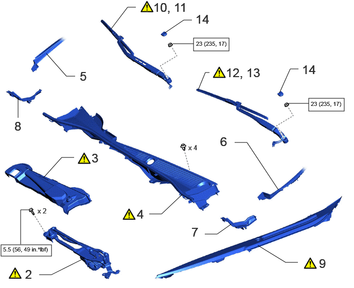
| Procedure | Part Name Code |
|
|
|
|
|---|---|---|---|---|---|
| 2 | WINDSHIELD WIPER MOTOR AND LINK ASSEMBLY | - | ()
|
- | - |
| 3 | FRONT WIPER MOTOR COVER | 85111A | ()
|
- | - |
| 4 | COWL TOP VENTILATOR LOUVER SUB-ASSEMBLY | 55708 | ()
|
- | - |
| 5 | LOWER WINDSHIELD MOULDING OUTSIDE | 75535A | - | - | - |
| 6 | LOWER WINDSHIELD MOULDING OUTSIDE LH | 75536D | - | - | - |
| 7 | COWL TOP VENTILATOR LOUVER PROTECTOR LH | 55783 | - | - | - |
| 8 | COWL TOP VENTILATOR LOUVER PROTECTOR RH | 55782 | - | - | - |
| 9 | FRONT UPPER FENDER PROTECTOR LH | 55826A | ()
|
- | - |
| 10 | INSTALL FRONT WIPER ARM AND BLADE ASSEMBLY RH (for LHD) | - | ()
|
- | - |
| 11 | INSTALL FRONT WIPER ARM AND BLADE ASSEMBLY RH (for RHD) | - | ()
|
- | - |
| 12 | INSTALL FRONT WIPER ARM AND BLADE ASSEMBLY LH (for LHD) | - | ()
|
||
| 13 | INSTALL FRONT WIPER ARM AND BLADE ASSEMBLY LH (for RHD) | - | ()
|
||
| 14 | FRONT WIPER ARM HEAD CAP | 53292B | - | - | - |
|
|
N*m (kgf*cm, ft.*lbf): Specified torque | - | - |
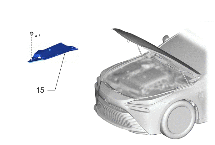
| Procedure | Part Name Code |
|
|
|
|
|---|---|---|---|---|---|
| 15 | UPPER RADIATOR SUPPORT SEAL | 53292A | - | - | - |
- NOTICE:
-
Make sure to hold the front wiper arm while lifting it, as lifting the front wiper arm by the front wiper blade may damage or deform the front wiper blade.
PROCEDURE

 85110
1.INSTALL WINDSHIELD WIPER MOTOR ASSEMBLY
|
|
|
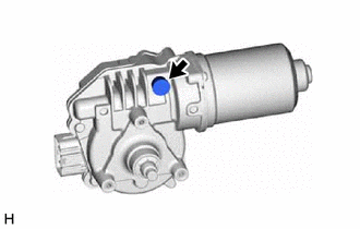
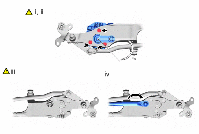
| *a | 45° | - | - |

|
Install in this Direction | 
|
Rotate in this Direction |

|
Apply MP Grease | - | - |
Install the windshield wiper motor assembly to the wiper link assembly with the 3 bolts.
- Torque:
- 5.4 N*m (55 kgf*cm, 48 in.*lbf)
Rotate the wiper crank arm of the windshield wiper motor assembly 45° in the clockwise direction (automatic stop position).
Apply MP grease to the wiper motor pivot.
Connect the No. 1 wiper link rod to the wiper motor pivot.
2.INSTALL WINDSHIELD WIPER MOTOR AND LINK ASSEMBLY
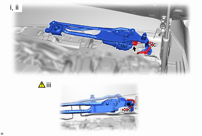
Connect the connector as shown in the illustration.
Attach the wire harness clamp and check that the wire harness is installed as shown in theillustration.
Temporarily install the front wiper motor and link to the vehicle and connect the wire harness clamp.
- NOTICE:
-
Do not damage the vehicle with the front wipermotor and link.
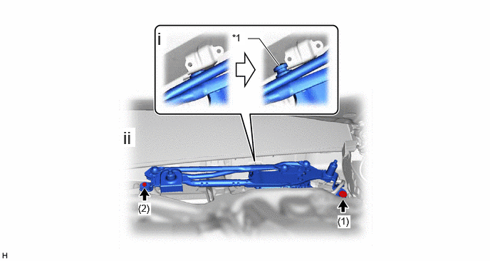
| *a | Motor Grommet | - | - |
Engage the motor grommet as shown in the illustration.
Install the windshield wiper motor and link assembly with the 2 bolts.
- Torque:
- 5.5 N*m (56 kgf*cm, 49 in.*lbf)
- HINT:
-
Tighten the bolts in the order shown in the illustration.
85111A
3.INSTALL FRONT WIPER MOTOR COVER
|
|
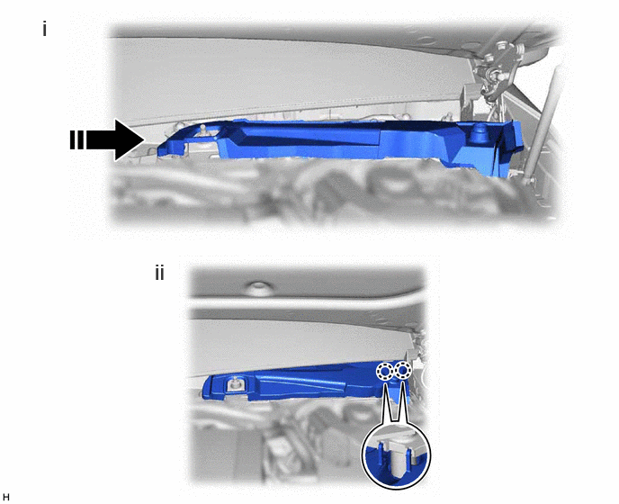
Install in this Direction | - | - |
Slide the wiper motor cover in the direction of the shown in the illustration to temporarily install it.
Attach the claw.
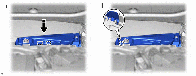
|
|
Install in this Direction | - | - |
55708
4.INSTALL COWL TOP VENTILATOR LOUVER SUB-ASSEMBLY
|
|
|
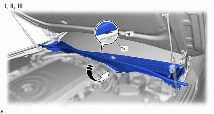
| *a | Guide | *b | Notch |
|
|
Install in this Direction | - | - |
Rotate the front of the cowl top ventilator louver sub-assembly and temporarily install the cowl top ventilator louver sub-assembly as shown in the illustration.
Align the positioning guide of the cowl top ventilator louver sub-assembly to the front window inner center moulding cutout
Hold the rear of the cowl top ventilator louver sub-assembly down and attach the cowl top ventilator louver sub-assembly to the front window inner center moulding.
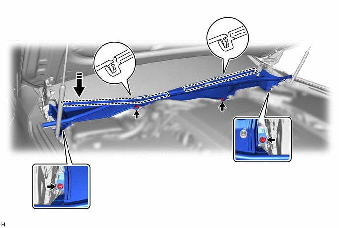
- HINT:
- ·
Check that the cowl top ventilator louver sub-assembly does not lift up.
·Check that the positioning guide is not pinched by the front window inner center moulding.
75535A
5.INSTALL LOWER WINDSHIELD MOULDING OUTSIDE
75536D
6.INSTALL LOWER WINDSHIELD MOULDING OUTSIDE LH
55783
7.INSTALL COWL TOP VENTILATOR LOUVER PROTECTOR LH
55782
8.INSTALL COWL TOP VENTILATOR LOUVER PROTECTOR RH
53826A
9.INSTALL FRONT UPPER FENDER PROTECTOR LH
10.INSTALL FRONT WIPER ARM AND BLADE ASSEMBLY RH (for LHD)
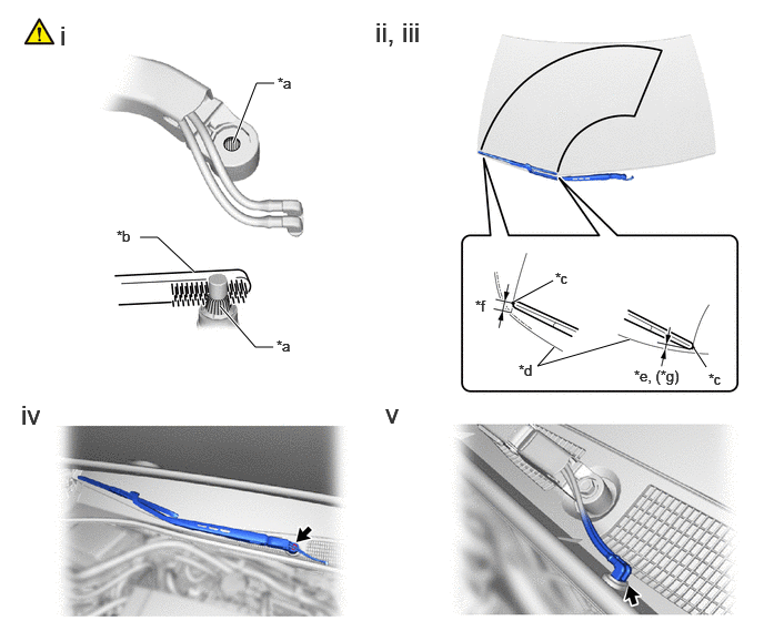
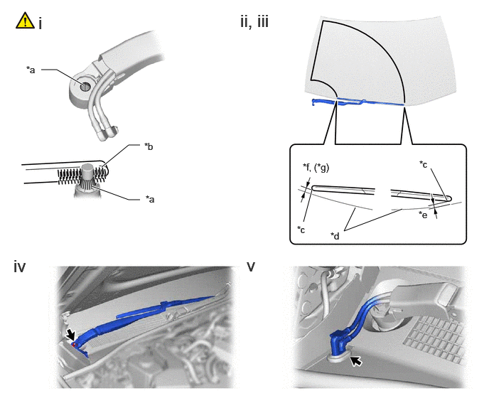
| *a | Serration | *b | Wire Brush |
| *c | Ceramic Dot | *d | Windshield Glass Edge |
| *e | 19.6 mm (Reference value) | *f | 9.4 to 24.4 mm |
| *g | Reference value | - | - |
When reusing the front wiper arm and blade assembly RH:
1. Clean the wiper arm serrations to remove any burrs, dirt, etc.
- NOTICE:
-
Do not grind down the wiper arm serrations.
Set the automatic stop position by the below procedure.
1. Turn the ignition switch to ON.
2. Operate the windshield wipers while spraying washer fluid onto the windshield glass. Make sure that the windshield wipers function properly and the wipers do not contact the vehicle body.
3. Turn the ignition switch off.
Temporarily install the front wiper arm and blade assembly RH with the nut to the position shown in the illustration.
Tighten the nut.
- Torque:
- 23 N*m (235 kgf*cm, 17 ft.*lbf)
- HINT:
-
Hold the arm hinge by hand when tightening the nut.
Connect the windshield washer hose assembly.
11.INSTALL FRONT WIPER ARM AND BLADE ASSEMBLY RH (for RHD)
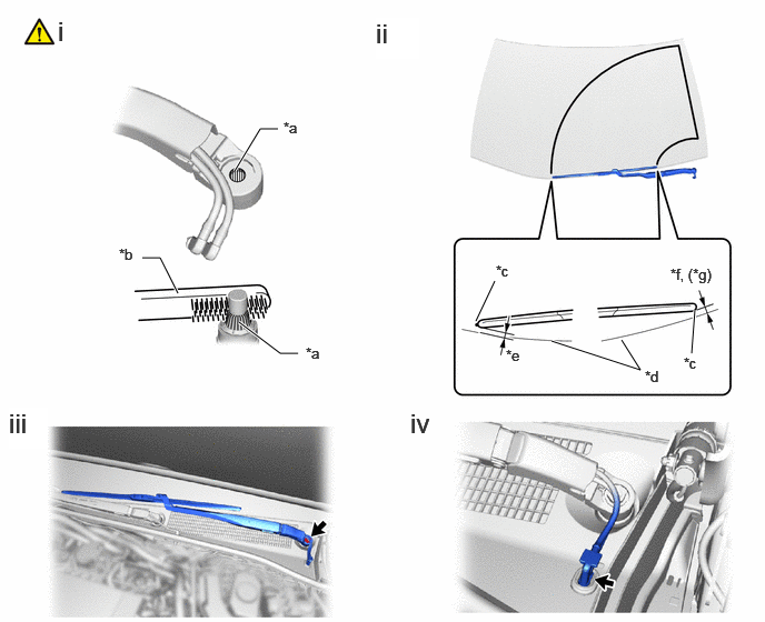
| *a | Serration | *b | Wire Brush |
| *c | Ceramic Dot | *d | Windshield Glass Edge |
| *e | 7.2 to 22.2 mm | *f | 11.6 mm |
| *g | Reference value | - | - |
When reusing the front wiper arm and blade assembly RH:
1. Clean the wiper arm serrations to remove any burrs, dirt, etc.
- NOTICE:
-
Do not grind down the wiper arm serrations.
Set the automatic stop position by the below procedure.
1. Turn the ignition switch to ON.
2. Operate the windshield wipers while spraying washer fluid onto the windshield glass. Make sure that the windshield wipers function properly and the wipers do not contact the vehicle body.
3. Turn the ignition switch off.
Temporarily install the front wiper arm and blade assembly RH with the nut to the position shown in the illustration.
Tighten the nut.
- Torque:
- 23 N*m (235 kgf*cm, 17 ft.*lbf)
- HINT:
-
Hold the arm hinge by hand when tightening the nut.
Connect the windshield washer hose assembly.
12.INSTALL FRONT WIPER ARM AND BLADE ASSEMBLY LH (for LHD)
| *a | Serration | *b | Wire Brush |
| *c | Ceramic Dot | *d | Windshield Glass Edge |
| *e | 7.2 to 22.2 mm | *f | 11.6 mm |
| *g | Reference value | - | - |
When reusing the front wiper arm and blade assembly LH:
1. Clean the wiper arm serrations to remove any burrs, dirt, etc.
- NOTICE:
-
Do not grind down the wiper arm serrations.
Temporarily install the front wiper arm and blade assembly LH with the nut to the position shown in the illustration.
Tighten the nut.
- Torque:
- 23 N*m (235 kgf*cm, 17 ft.*lbf)
- HINT:
-
Hold the arm hinge by hand when tightening the nut.
Connect the windshield washer hose assembly.
13.INSTALL FRONT WIPER ARM AND BLADE ASSEMBLY LH (for RHD)
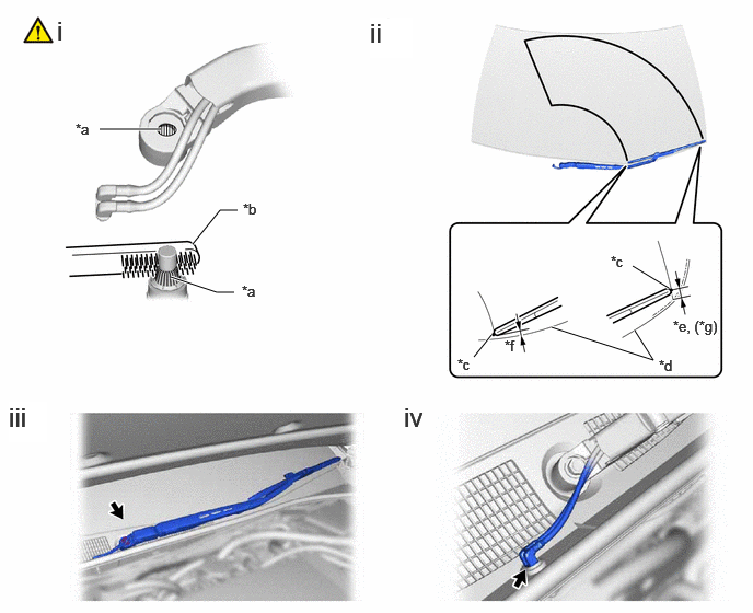
| *a | Serration | *b | Wire Brush |
| *c | Ceramic Dot | *d | Windshield Glass Edge |
| *e | 19.6 mm (Reference value) | *f | 9.4 to 24.4 mm |
| *g | Reference value | - | - |
When reusing the front wiper arm and blade assembly LH:
1. Clean the wiper arm serrations to remove any burrs, dirt, etc.
- NOTICE:
-
Do not grind down the wiper arm serrations.
Temporarily install the front wiper arm and blade assembly LH with the nut to the position shown in the illustration.
Tighten the nut.
- Torque:
- 23 N*m (235 kgf*cm, 17 ft.*lbf)
- HINT:
-
Hold the arm hinge by hand when tightening the nut.
Connect the windshield washer hose assembly.
85292B
14.INSTALL FRONT WIPER ARM HEAD CAP
53292A
15.INSTALL UPPER RADIATOR SUPPORT SEAL