COOLING COOLING FAN SYSTEM Cooling Fan Circuit
DESCRIPTION
For the cooling fan, the EV control ECU calculates the fan speed needed for cooling based on the FC stack assembly coolant temperature, A/C switch, air conditioner refrigerant pressure and vehicle speed information, and sends a control signal to the cooling fan with motor assembly. Based on the duty ratio in the signal from the EV control ECU, the continuously variable speed of the fan with motor assembly is controlled. In response to driving conditions, the EV control ECU sends a signal to the fan with motor assembly to control fan speed to the optimal level, achieving a balance between cooling performance and silent operation.
WIRING DIAGRAM
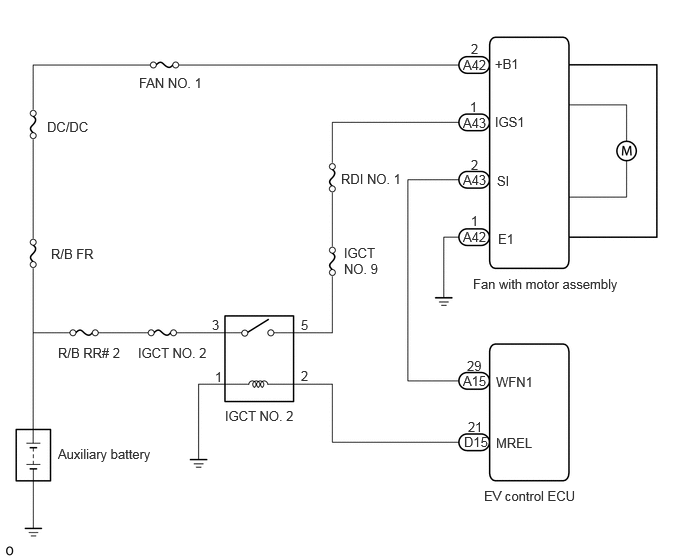
CAUTION / NOTICE / HINT
- NOTICE:
- ·
Inspect the fuses for circuits related to this system before performing the following procedure.
·Make sure to perform the necessary procedures (adjustment, calibration, initialization, or registration) after parts related to the cooling fan system have been removed/installed or replaced.
Click hereGeneral>SETUP>WHEN REPLACING OR REMOVING/INSTALLING PARTS>WORK PROCEDURE
·This vehicle performs FC system shutdown process after turning the ignition switch off from ON (READY). Therefore, after the ignition switch is turned off from ON (READY), do not perform any work on the electrical system for at least 10 minutes including removing connectors or disconnecting the negative (-) auxiliary battery terminal.
PROCEDURE
According to the display on the GTS, perform the Active Test.
- Powertrain > EV > Active Test
-
Tester Display Control the Radiator Fan 1 - 50004 397 18
| Tester Operation | Fan Operation |
|---|---|
| ON | Cooling fan operate |
| OFF | Cooling fan stop |
- Result:
Result Proceed to OK A NG (Fan does not operate) B NG (Fan does not stop) C
A
B
C
Disconnect the A15 EV control ECU connector.
Disconnect the A43 fan with motor assembly connector.
Measure the resistance according to the value(s) in the table below.
- Standard Resistance:
Tester Connection Condition Specified Condition Click Location & Routing(A15,A43)Location & Routingewd_type=routing;type=c,c;code=A15,A43
Click Connector(A15)Instrument Panel>Front Compartment Main Wire>EV Control ECUewd_type=component;type=c;code=A15;pinno=29
Click Connector(A43)Engine Compartment>Front Compartment Main Wire / No. 3 Front Compartment Wire / No. 4 Front Compartment Wire>Fan with Motor Assemblyewd_type=component;type=c;code=A43;pinno=2
A15-29(WFN1) - A43-2(SI) Always Below 1 Ω A15-29(WFN1) and A43-2(SI) - Body ground and other terminals Always 10 kΩ or higher
- Result:
Proceed to OK NG
OK
NG
Disconnect the A43 fan with motor assembly connector.
According to the display on the GTS, perform the Active Test.
- Powertrain > EV > Active Test
-
Tester Display Control the Radiator Fan 1 - 50004 397 18
Operate the fan with motor assembly using the Active Test function and measure the resistance according to the value(s) in the table below.
- Standard Resistance:
Tester Connection Condition Specified Condition Click Location & Routing(A43)Location & Routingewd_type=routing;type=c;code=A43
Click Connector(A43)Engine Compartment>Front Compartment Main Wire / No. 3 Front Compartment Wire / No. 4 Front Compartment Wire>Fan with Motor Assemblyewd_type=component;type=c;code=A43;pinno=2
A43-2 (SI) - Body ground Before Active Test (OFF) → During Active Test (ON) Before Active Test (OFF): Resistance is stable → During Active Test (ON): Resistance fluctuates*
- HINT:
-
*: Using the Active Test, duty control of the transistors in the EV control ECU will be performed. Due to the duty control, resistance of the WFN1 terminal will be unstable during the Active Test. If the resistance is stable before the Active Test and fluctuates while performing the Active Test, it can be determined that the transistor is operating. If the transistor does not operate during the Active Test, the EV control ECU may be malfunctioning.
- Result:
Proceed to OK NG
OK
NG
Disconnect the A42 fan with motor assembly connector.
Measure the voltage according to the value(s) in the table below.
- Standard Voltage:
Tester Connection Condition Specified Condition Click Location & Routing(A42)Location & Routingewd_type=routing;type=c;code=A42
Click Connector(A42)Engine Compartment>Front Compartment Main Wire / No. 3 Front Compartment Wire / No. 4 Front Compartment Wire>Fan with Motor Assemblyewd_type=component;type=c;code=A42;pinno=2,1
A42-2(+B1) - A42-1(E1) Always 11 to 14V
- Result:
Proceed to OK NG
OK
NG
Disconnect the A43 fan with motor assembly connector.
Turn the ignition switch on (IG).
Measure the voltage according to the value(s) in the table below.
- Standard Resistance:
Tester Connection Condition Specified Condition Click Location & Routing(A43)Location & Routingewd_type=routing;type=c;code=A43
Click Connector(A43)Engine Compartment>Front Compartment Main Wire / No. 3 Front Compartment Wire / No. 4 Front Compartment Wire>Fan with Motor Assemblyewd_type=component;type=c;code=A43;pinno=1
A43-1(IGS1) - Body ground Ignition switch on (IG) 11 to 14V
- Result:
Proceed to OK NG
OK
NG
Disconnect the A43 fan with motor assembly connector.
Remove the IGCT NO. 2 relay from the luggage room relay block.
Measure the resistance according to the value(s) in the table below.
- Standard Resistance:
Tester Connection Condition Specified Condition Click Location & Routing(A43)Location & Routingewd_type=routing;type=c;code=A43
Click Connector(A43)Engine Compartment>Front Compartment Main Wire / No. 3 Front Compartment Wire / No. 4 Front Compartment Wire>Fan with Motor Assemblyewd_type=component;type=c;code=A43;pinno=1
A43-1(IGS1) - 5(IGCT NO. 2 relay holder) Always Below 1 Ω
- Result:
Proceed to OK NG
OK
Click hereEngine / Hybrid System>HYBRID / BATTERY CONTROL>HYBRID CONTROL SYSTEM>ECU Power Source Circuit
NG
Disconnect the A42 fan with motor assembly connector.
Measure the resistance according to the value(s) in the table below.
- Standard Resistance:
Tester Connection GTS Operation Specified Condition Click Location & Routing(A42)Location & Routingewd_type=routing;type=c;code=A42
Click Connector(A42)Engine Compartment>Front Compartment Main Wire / No. 3 Front Compartment Wire / No. 4 Front Compartment Wire>Fan with Motor Assemblyewd_type=component;type=c;code=A42;pinno=1
A42-1(E1) - Body ground Always Below 1 Ω
- Result:
Proceed to OK NG
OK
NG
Disconnect the A15 EV control ECU connector.
Disconnect the A43 fan with motor assembly.
Measure the resistance according to the value(s) in the table below.
- Standard Resistance:
Tester Connection Condition Specified Condition Click Location & Routing(A15,A43)Location & Routingewd_type=routing;type=c,c;code=A15,A43
Click Connector(A15)Instrument Panel>Front Compartment Main Wire>EV Control ECUewd_type=component;type=c;code=A15;pinno=29
Click Connector(A43)Engine Compartment>Front Compartment Main Wire / No. 3 Front Compartment Wire / No. 4 Front Compartment Wire>Fan with Motor Assemblyewd_type=component;type=c;code=A43;pinno=2
A15-29 (WFN1) - A43-2 (SI) Always Below 1 Ω A15-29 (WFN1) and A43-2 (SI) - Other terminals and Body ground Always 10 kΩ or higher
- Result:
Proceed to OK NG
OK
NG
Disconnect the A43 fan with motor assembly.
According to the display on the GTS, perform the Active Test.
- Powertrain > EV > Active Test
-
Tester Display Control the Radiator Fan 1 - 50004 397 18
Operate the fan with motor assembly using the Active Test function and measure the resistance according to the value(s) in the table below.
- Standard Resistance:
Tester Connection Condition Specified Condition Click Location & Routing(A43)Location & Routingewd_type=routing;type=c;code=A43
Click Connector(A43)Engine Compartment>Front Compartment Main Wire / No. 3 Front Compartment Wire / No. 4 Front Compartment Wire>Fan with Motor Assemblyewd_type=component;type=c;code=A43;pinno=2
A43-2(SI) - Body ground Before Active Test (OFF) → During Active Test (ON) Before Active Test (OFF): Resistance is stable → During Active Test (ON): Resistance fluctuates*
- HINT:
-
*: Using the Active Test, duty control of the transistors in the EV control ECU will be performed. Due to the duty control, resistance of the WFN1 terminal will be unstable during the Active Test. If the resistance is stable before the Active Test and fluctuates while performing the Active Test, it can be determined that the transistor is operating. If the transistor does not operate during the Active Test, the EV control ECU may be malfunctioning.
- Result:
Proceed to OK NG
OK
NG