HYBRID / BATTERY CONTROL HYBRID VEHICLE CONTROL ECU REMOVAL
CAUTION / NOTICE / HINT
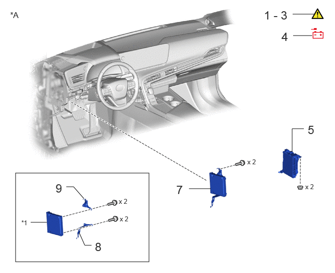
| Procedure | Part Name Code | 
|

|

|
|
|---|---|---|---|---|---|
| 1 | PRECAUTION | - | ( ) |
- | - |
| 2 | WHEN REPLACING EV CONTROL ECU | - | ()
|
- | - |
| 3 | ECU DATA SAVE | - | ()
|
- | - |
| 4 | DISCONNECT CABLE FROM NEGATIVE AUXILIARY BATTERY TERMINAL | - | - | - | - |
| 5 | DRIVER SIDE JUNCTION BLOCK ASSEMBLY WITH MAIN BODY ECU | - | - | - | - |
| 7 | EV CONTROL ECU WITH EV CONTROL ECU BRACKET | - | - | - | - |
| 8 | NO. 1 EV CONTROL ECU BRACKET | 896B7 | - | - | - |
| 9 | NO. 2 EV CONTROL ECU BRACKET | 89998D | - | - | - |
| *A | for LHD | - | - |
| *1 | EV CONTROL ECU | - | - |
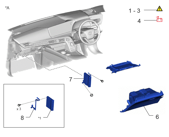
| Procedure | Part Name Code |
|
|
|
|
|---|---|---|---|---|---|
| 1 | PRECAUTION | - | ()
|
- | - |
| 2 | WHEN REPLACING EV CONTROL ECU | - | ()
|
- | - |
| 3 | ECU DATA SAVE | - | ()
|
- | - |
| 4 | DISCONNECT CABLE FROM NEGATIVE AUXILIARY BATTERY TERMINAL | - | - | - | - |
| 6 | GLOVE COMPARTMENT DOOR ASSEMBLY | - | - | - | - |
| 7 | EV CONTROL ECU WITH EV CONTROL ECU BRACKET | - | - | - | - |
| 8 | NO. 1 EV CONTROL ECU BRACKET | 896B7 | - | - | - |
| *A | for RHD | - | - |
| *1 | EV CONTROL ECU | - | - |
CAUTION / NOTICE / HINT
The necessary procedures (adjustment, calibration, initialization, or registration) that must be performed after parts are removed and installed, or replaced during EV control ECU removal/installation are shown below.
| Replaced Part or Performed Procedure | Necessary Procedures | Effect/Inoperative Function when Necessary Procedure not Performed | Link |
|---|---|---|---|
| EV control ECU | Vehicle Identification Number (VIN) registration | DTC P063051 output | ()
|
| Perform code registration | Does not change to on (READY) | See Service Bulletin for the registration method. | |
| ECU data save | Notifications are not given at the correct maintenance distance | ()
|
|
·
ECU data write ·
Ion exchanger maintenance distance setting |
()
|
||
| Update ECU security key | Vehicle control history (RoB) are stored | ()
|
|
| Auxiliary battery terminal is disconnected/reconnected | Memorize steering angle neutral point | Parking assist monitor system | ()
|
| Panoramic view monitor system | ()
|
- HINT:
-
When the cable is disconnected/reconnected to the auxiliary battery terminal, systems temporarily stop operating. However, each system has a function that completes learning the first time the system is used.
- ·
Learning completes when vehicle is driven
Effect/Inoperative Function When Necessary Procedures are not Performed Necessary Procedures Link Lane tracing assist system Drive the vehicle straight ahead at 35 km/h (22 mph) or more for 5 seconds or more. ( )
Pre-collision system Adaptive high beam system
- ·
Learning completes when vehicle is operated normally
Effect/Inoperative Function When Necessary Procedures are not Performed Necessary Procedures Link Air conditioning system After the ignition switch is turned to ON, the servo motor and expansion valve standard position is recognized. -
PROCEDURE

 1. PRECAUTION
|
|
|
2. WHEN REPLACING EV CONTROL ECU
HV battery learning values are stored in the battery ECU assembly and EV control ECU and are used to detect malfunctions and illuminate the hybrid battery indicator light in the combination meter assembly. When either of these ECUs is replaced, the new ECU receives the HV battery learning values from the other ECU and stores them.
|
|
|
Procedure when replacing both battery ECU assembly and EV control ECU:
Disconnect the cable from the negative (-) auxiliary battery terminal.
Replace either ECU.
Connect the cable to the negative (-) auxiliary battery terminal.
Turn the ignition switch on (READY) and wait for 5 minutes or more.
Turn the ignition switch off and disconnect the cable from the negative (-) auxiliary battery terminal.
Replace the other ECU.
Connect the cable to the negative (-) auxiliary battery terminal.
Check that the ignition switch can be turned on (READY).
- HINT:
-
If the battery ECU assembly and EV control ECU are replaced at the same time without following the above procedure, replace either of the ECUs with its original one and then replace it again by following the above procedure. If the correct procedure is not followed, perform the procedure again from the beginning.
3. ECU DATA SAVE
|
|
|
ECU data save
- HINT:
-
This function saves the ion exchanger maintenance distance data stored in the EV control ECU to the GTS.
According to the display on the GTS, save the ion exchanger maintenance distance data to the GTS.
- Powertrain > EV > Utility
-
Tester Display ECU Data Save - 50005 397 5695
If the data is not saved to the GTS normally, perform the ion exchanger maintenance distance settings.
Click hereEngine / Hybrid System>HYBRID / BATTERY CONTROL>HYBRID VEHICLE CONTROL ECU>INSTALLATION
4.DISCONNECT CABLE FROM NEGATIVE AUXILIARY BATTERY TERMINAL
5.REMOVE DRIVER SIDE JUNCTION BLOCK ASSEMBLY WITH MAIN BODY ECU (for LHD)
6.REMOVE GLOVE COMPARTMENT DOOR ASSEMBLY (for RHD)
7.REMOVE EV CONTROL ECU WITH EV CONTROL ECU BRACKET

| *A | for LHD | - | - |
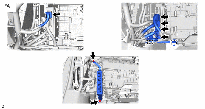
| *A | for RHD | - | - |
896B7
8.REMOVE NO. 1 EV CONTROL ECU BRACKET
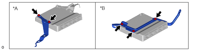
| *A | for LHD | *B | for RHD |
89988D
9.REMOVE NO. 2 EV CONTROL ECU BRACKET (for LHD)