AUDIO / VIDEO AUDIO AND VISUAL SYSTEM B15C3 Speaker Output Short
DESCRIPTION
This DTC is stored when a malfunction occurs in the speakers.
| DTC No. | Detection Item | DTC Detection Condition | Trouble Area | DTC Output from | Priority |
|---|---|---|---|---|---|
| B15C3 | Speaker Output Short | A short is detected in the speaker output circuit | ·
Harness or connector ·
Speaker ·
Radio and display receiver assembly |
Navigation System | A |
WIRING DIAGRAM
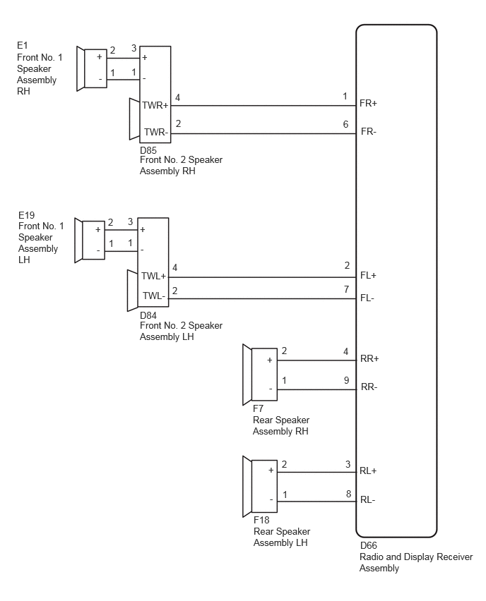
PROCEDURE
Pre-procedure1
Clear the DTCs.
- Body Electrical > Navigation System > Clear DTCs
- 50002 212
Procedure1
Recheck for DTCs and check that no DTCs are output.
- Body Electrical > Navigation System > Trouble Codes
- 50001 212
- Result:
Result Proceed to DTCs are not output A DTCs are output B
Post-procedure1
None
A
Click hereGeneral>INTRODUCTION>HOW TO TROUBLESHOOT ECU CONTROLLED SYSTEMS>HOW TO PROCEED WITH TROUBLESHOOTING
B
Pre-procedure1
Disconnect the D66 radio and display receiver assembly connector.
Disconnect the E1 and E19 front No. 1 speaker assembly connectors.
Disconnect the D85 and D84 front No. 2 speaker assembly connectors.
Disconnect the F7 and F18 rear speaker assembly connectors.
Procedure1
Measure the resistance according to the value(s) in the table below.
- Standard Resistance:
Tester Connection Condition Specified Condition Click Location & Routing(D66,D85,D84,E1,E19,F7,F18)Location & Routingewd_type=routing;type=c,c,c,c,c,c,c;code=D66,D85,D84,E1,E19,F7,F18
Click Connector(D66)Instrument Panel>Instrument Panel Wire>Radio Receiver Assemblyewd_type=component;type=c;code=D66;pinno=1,6,2,7,4,9,3,8
Click Connector(D85)Instrument Panel>Instrument Panel Wire>Front No. 3 Speaker Assembly LHewd_type=component;type=c;code=D85;pinno=4,2,3,1
Click Connector(D84)Instrument Panel>Instrument Panel Wire>Front No. 3 Speaker Assembly RHewd_type=component;type=c;code=D84;pinno=4,2,3,1
Click Connector(E1)Body>Front Door Wire LH / Front Door Wire RH>Front No. 1 Speaker Assembly RHewd_type=component;type=c;code=E1;pinno=2,1
Click Connector(E19)Body>Front Door Wire LH / Front Door Wire RH>Front No. 1 Speaker Assembly LHewd_type=component;type=c;code=E19;pinno=2,1
Click Connector(F7)Body>No. 1 Rear Door Wire / No. 2 Rear Door Wire>Rear Speaker Assembly RHewd_type=component;type=c;code=F7;pinno=2,1
Click Connector(F18)Body>No. 1 Rear Door Wire / No. 2 Rear Door Wire>Rear Speaker Assembly LHewd_type=component;type=c;code=F18;pinno=2,1
D66-1 (FR+) - D85-4 (TWR+) Always Below 1 Ω D66-6 (FR-) - D85-2 (TWR-) Always Below 1 Ω D66-2 (FL+) - D84-4 (TWL+) Always Below 1 Ω D66-7 (FL-) - D84-2 (TWL-) Always Below 1 Ω D85-3 (+) - E1-2 (+) Always Below 1 Ω D85-1 (-) - E1-1 (-) Always Below 1 Ω D84-3 (+) - E19-2 (+) Always Below 1 Ω D84-1 (-) - E19-1 (-) Always Below 1 Ω D66-4 (RR+) - F7-2 (+) Always Below 1 Ω D66-9 (RR-) - F7-1 (-) Always Below 1 Ω D66-3 (RL+) - F18-2 (+) Always Below 1 Ω D66-8 (RL-) - F18-1 (-) Always Below 1 Ω D66-1 (FR+) - Body ground Always 10 kΩ or higher D66-6 (FR-) - Body ground Always 10 kΩ or higher D66-2 (FL+) - Body ground Always 10 kΩ or higher D66-7 (FL-) - Body ground Always 10 kΩ or higher D85-3 (+) - Body ground Always 10 kΩ or higher D85-1 (-) - Body ground Always 10 kΩ or higher D84-3 (+) - Body ground Always 10 kΩ or higher D84-1 (-) - Body ground Always 10 kΩ or higher D66-4 (RR+) - Body ground Always 10 kΩ or higher D66-9 (RR-) - Body ground Always 10 kΩ or higher D66-3 (RL+) - Body ground Always 10 kΩ or higher D66-8 (RL-) - Body ground Always 10 kΩ or higher
- Result:
Proceed to OK NG
Post-procedure1
None
OK
NG
- Result:
Proceed to OK NG
OK
NG
- Result:
Proceed to OK NG
OK
NG
Pre-procedure1
Replace the front No. 2 speaker assembly with a new or known good one.
Clear the DTCs.
- Body Electrical > Navigation System > Clear DTCs
- 50002 212
Procedure1
Recheck for DTCs and check that no DTCs are output.
- Body Electrical > Navigation System > Trouble Codes
- 50001 212
- Result:
Result Proceed to DTCs are not output A DTCs are output B
Post-procedure1
None
A
B