HYBRID / BATTERY CONTROL HYBRID CONTROL SYSTEM P0C3812 DC/DC Converter Temperature Sensor "A" Circuit Short to Battery P0C3814 DC/DC Converter Temperature Sensor "A" Circuit Short to Ground or Open P0C3D12 DC/DC Converter Temperature Sensor "B" Circuit Short to Battery P0C3D14 DC/DC Converter Temperature Sensor "B" Circuit Short to Ground or Open
DESCRIPTION
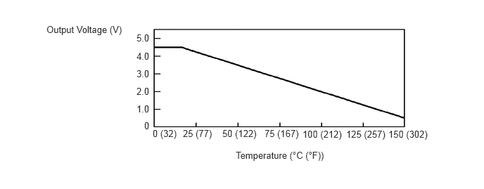
The MG ECU, which is built into in the inverter with converter assembly, detects the boost converter temperature using the temperature sensor in the boost converter. The boost converter temperature sensor outputs voltage that changes between 0.5 and 4.5 V according to changes in temperature. The higher the boost converter temperature is, the lower the output voltage will be. Conversely, the lower the boost converter temperature is, the higher the output voltage will be. The MG ECU controls load based on signals sent from the boost converter temperature sensor to prevent overheating. The MG ECU detects malfunctions in the boost converter temperature sensor and its wiring.
| DTC No. | Detection Item | DTC Detection Condition | Trouble Area | Warning Indicate | DTC Output from | Priority |
|---|---|---|---|---|---|---|
| P0C3812 | DC/DC Converter Temperature Sensor "A" Circuit Short to Battery | Short to +B in the boost converter temperature sensor (upper) signal circuit
(1 trip detection logic) |
Inverter with converter assembly | Master Warning:
Comes on |
EV | A |
| P0C3814 | DC/DC Converter Temperature Sensor "A" Circuit Short to Ground or Open | Open or short to ground in the boost converter temperature sensor (upper) signal circuit
(1 trip detection logic) |
Inverter with converter assembly | Master Warning:
Comes on |
EV | A |
| P0C3D12 | DC/DC Converter Temperature Sensor "B" Circuit Short to Battery | Short to +B in the boost converter temperature sensor (lower) signal circuit
(1 trip detection logic) |
Inverter with converter assembly | Master Warning:
Comes on |
EV | A |
| P0C3D14 | DC/DC Converter Temperature Sensor "B" Circuit Short to Ground or Open | Open or short to ground in the boost converter temperature sensor (lower) signal circuit
(1 trip detection logic) |
Inverter with converter assembly | Master Warning:
Comes on |
EV | A |
| DTC No. | Data List |
|---|---|
| P0C3812 | Boosting Converter Temperature (Upper) |
| P0C3814 | |
| P0C3D12 | Boosting Converter Temperature (Lower) |
| P0C3D14 |
CONFIRMATION DRIVING PATTERN
- HINT:
-
After repairs have been completed, clear the DTCs and then check that the vehicle has returned to normal by performing the following All Readiness check procedure.
-
Click hereEngine / Hybrid System>HYBRID / BATTERY CONTROL>HYBRID CONTROL SYSTEM>UTILITY
Turn the ignition switch to ON and wait for 5 seconds or more.
Enter the following menus: Powertrain / EV / Utility / All Readiness.
Check the DTC judgment result.
- HINT:
- ·
If the judgment result shows NORMAL, the system is normal.
·If the judgment result shows ABNORMAL, the system has a malfunction.
·If the judgment result shows INCOMPLETE, perform driving pattern again.
CAUTION / NOTICE / HINT
- NOTICE:
- ·
This vehicle performs FC system shutdown process after turning the ignition switch off from ON (READY). Therefore, after the ignition switch is turned off from ON (READY), do not perform any work on the electrical system for at least 10 minutes including removing connectors or disconnecting the negative (-) auxiliary battery terminal.
·When the EV control ECU determines that the temperature of FC system components is below 0°C (32°F) when the vehicle is parked with the ignition switch off, it operates the FC air compressor, hydrogen pump and FC cooling water pump for a maximum of 180 seconds to drain the FC stack assembly. When performing inspection or repairs with the ignition switch off (not ON or ON (READY)), disconnect the cable from the negative (-) auxiliary battery terminal before performing work. (If the auxiliary battery voltage is needed to conduct inspection, perform the inspection in an environment with an ambient temperature of 10°C (50°F) or higher.)
PROCEDURE
- Result:
Proceed to NEXT
NEXT