HYBRID / BATTERY CONTROL INVERTER WITH CONVERTER REMOVAL
CAUTION / NOTICE / HINT
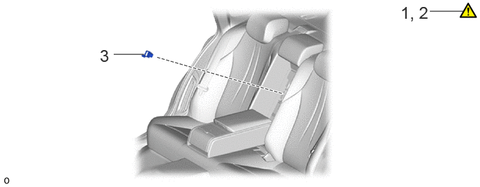
| Procedure | Part Name Code | 
|

|

|
|
|---|---|---|---|---|---|
| 1 | PRECAUTION | - | ( ) |
- | - |
| 2 | CAUTIONS FOR HIGH VOLTAGE SYSTEM COMPONENTS | - | ()
|
- | - |
| 3 | SERVICE PLUG GRIP | G3834 | - | - | - |
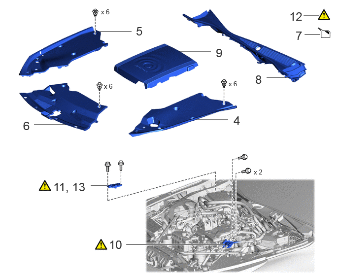
| Procedure | Part Name Code |
|
|
|
|
|---|---|---|---|---|---|
| 4 | UPPER RADIATOR SUPPORT SEAL | 53292A | - | - | - |
| 5 | RADIATOR COVER PLATE | 53291B | - | - | - |
| 6 | LOWER RADIATOR AIR DEFLECTOR | 53295 | - | - | - |
| 7 | DRAIN COOLANT (for Inverter) | - | - | ()
|
- |
| 8 | COWL TOP VENTILATOR LOUVER SUB-ASSEMBLY | 55708 | - | - | - |
| 9 | FC STACK COVER SUB-ASSEMBLY | 1A906 | - | - | - |
| 10 | FC CONVERTER POWER OUTLET CABLE (INVERTER WITH CONVERTER ASSEMBLY) | G9200A | ()
|
- | - |
| 11 | REMOVE CONNECTOR COVER ASSEMBLY | - | ()
|
- | - |
| 12 | CHECK TERMINAL VOLTAGE | - | ()
|
- | - |
| 13 | TEMPORARILY INSTALL CONNECTOR COVER ASSEMBLY | - | ()
|
- | - |
| Procedure | Part Name Code |
|
|
|
|
|---|---|---|---|---|---|
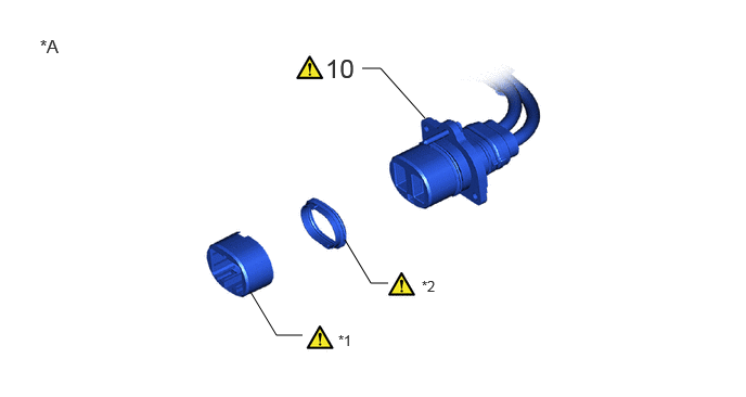
| 10 | FC CONVERTER POWER OUTLET CABLE (INVERTER WITH CONVERTER ASSEMBLY) | G9200A | ()
|
- | - |
| *A | If the FC converter power outlet front holder and FC converter power outlet front gasket are left in the stack, remove them using the following procedure | - | - |
| *1 | FC CONVERTER POWER OUTLET FRONT HOLDER | *2 | FC CONVERTER POWER OUTLET FRONT GASKET |
| Procedure | Part Name Code |
|
|
|
|
|---|---|---|---|---|---|
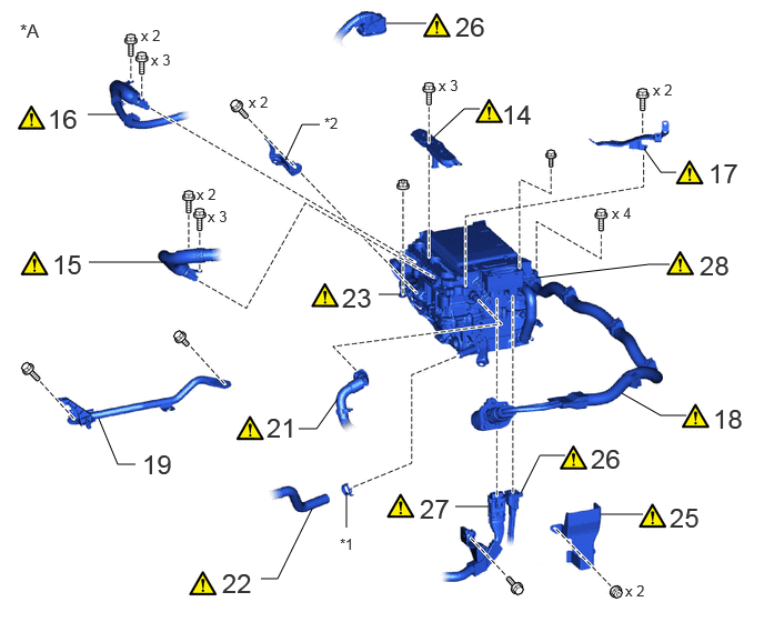
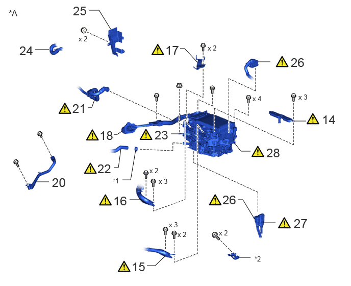
| 14 | INVERTER TERMINAL COVER | G9223B | ()
|
- | - |
| 15 | FC AIR COMPRESSOR MOTOR CABLE ASSEMBLY | 17A90 | ()
|
- | - |
| 16 | NO. 2 BATTERY PACK WIRE | 821H3B | ()
|
- | - |
| 17 | INVERTER MOTOR CABLE BRACKET ASSEMBLY | G1240C | ()
|
- | - |
| 18 | FC CONVERTER POWER OUTLET CABLE (INVERTER WITH CONVERTER ASSEMBLY) | G9200A | ()
|
- | - |
| 19 | FENDER APRON BRACE SUB-ASSEMBLY RH | 53705F | - | - | - |
| 21 | NO. 1 FC INVERTER COOLING HOSE SUB-ASSEMBLY | G90A1 | ()
|
- | - |
| 22 | NO. 3 FC INVERTER COOLING HOSE | G91C3 | ()
|
- | - |
| 23 | INVERTER BUS-BAR PLATE SUB-ASSEMBLY | G9205A | ()
|
- | - |
| 25 | WIRE HARNESS CLAMP BRACKET | - | - | - | - |
| 26 | FRONT COMPARTMENT MAIN WIRE | 82111C | ()
|
- | - |
| 27 | FC JUNCTION CABLE | G9A2C | ()
|
- | - |
| 28 | INVERTER WITH CONVERTER ASSEMBLY | G9200A | ()
|
- | - |
| *A | for LHD | - | - |
| *1 | HOSE CLIP | *2 | NO. 6 INVERTER BRACKET |
| Procedure | Part Name Code |
|
|
|
|
|---|---|---|---|---|---|
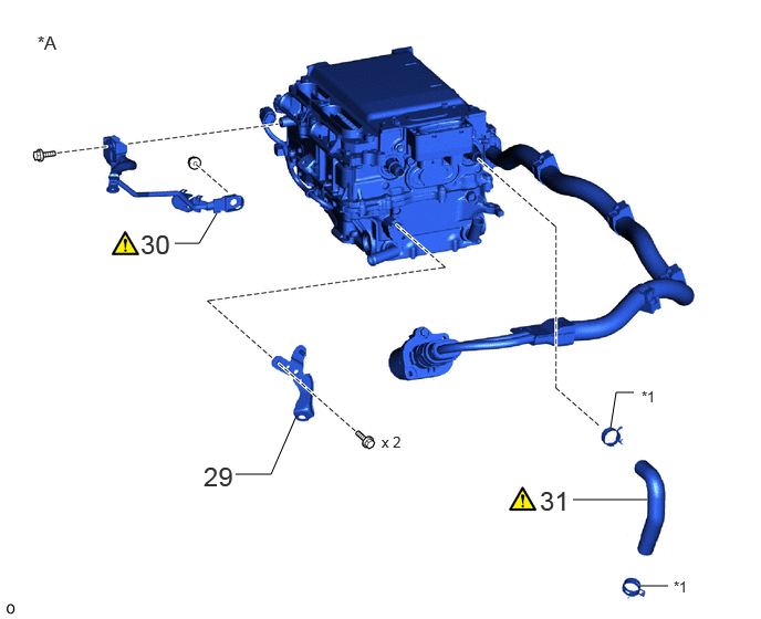
| 14 | INVERTER TERMINAL COVER | G9223B | ()
|
- | - |
| 15 | FC AIR COMPRESSOR MOTOR CABLE ASSEMBLY | 17A90 | ()
|
- | - |
| 16 | NO. 2 BATTERY PACK WIRE | 821H3B | ()
|
- | - |
| 17 | INVERTER MOTOR CABLE BRACKET ASSEMBLY | G1240C | ()
|
- | - |
| 18 | FC CONVERTER POWER OUTLET CABLE (INVERTER WITH CONVERTER ASSEMBLY) | G9200A | ()
|
- | - |
| 20 | FENDER APRON BRACE SUB-ASSEMBLY LH | 53706A | - | - | - |
| 21 | NO. 1 FC INVERTER COOLING HOSE SUB-ASSEMBLY | G90A1 | ()
|
- | - |
| 22 | NO. 3 FC INVERTER COOLING HOSE | G91C3 | ()
|
- | - |
| 23 | INVERTER BUS-BAR PLATE SUB-ASSEMBLY | G9205A | ()
|
- | - |
| 24 | WATER HOSE SUB-ASSEMBLY C | 87209C | - | - | - |
| 25 | WIRE HARNESS CLAMP BRACKET | - | - | - | - |
| 26 | FRONT COMPARTMENT MAIN WIRE | 82111C | ()
|
- | - |
| 27 | FC JUNCTION CABLE | G9A2C | ()
|
- | - |
| 28 | INVERTER WITH CONVERTER ASSEMBLY | G9200A | ()
|
- | - |
| *A | for RHD | - | - |
| *1 | HOSE CLIP | *2 | NO. 6 INVERTER BRACKET |
| Procedure | Part Name Code |
|
|
|
|
|---|---|---|---|---|---|
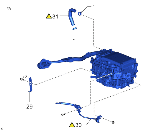
| 29 | NO. 4 INVERTER BRACKET | G9217A | - | - | - |
| 30 | INVERTER BUS-BAR PLATE SUB-ASSEMBLY | G9205A | ()
|
- | - |
| 31 | NO. 1 INVERTER COOLING HOSE | - | ()
|
- | - |
| *A | for LHD | - | - |
| *1 | HOSE CLIP | - | - |
| Procedure | Part Name Code |
|
|
|
|
|---|---|---|---|---|---|
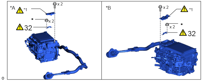
| 29 | NO. 4 INVERTER BRACKET | G9217A | - | - | - |
| 30 | INVERTER BUS-BAR PLATE SUB-ASSEMBLY | G9205A | ()
|
- | - |
| 31 | NO. 1 INVERTER COOLING HOSE | - | ()
|
- | - |
| *A | for RHD | - | - |
| *1 | HOSE CLIP | - | - |
| Procedure | Part Name Code |
|
|
|
|
|---|---|---|---|---|---|
| 32 | HIGH VOLTAGE FUSE | - | ()
|
- | - |
| *A | for LHD | *B | for RHD |
| *1 | CONNECTOR COVER ASSEMBLY | - | - |
| ● | Non-reusable part | - | - |
CAUTION / NOTICE / HINT
The necessary procedures (adjustment, calibration, initialization, or registration) that must be performed after parts are removed and installed, or replaced during inverter with converter assembly removal/installation are shown below.
| Replaced Part or Performed Procedure | Necessary Procedures | Effect/Inoperative Function when Necessary Procedure not Performed | Link |
|---|---|---|---|
| Auxiliary battery terminal is disconnected/reconnected | Memorize steering angle neutral point | Parking assist monitor system | ()
|
| Panoramic view monitor system | ()
|
- CAUTION:
- ·
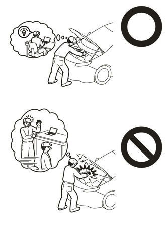
Orange wire harnesses and connectors indicate high-voltage circuits. To prevent electric shock, always follow the procedure described in the repair manual.
Click hereEngine / Hybrid System>HYBRID / BATTERY CONTROL>HYBRID CONTROL SYSTEM>PRECAUTION
·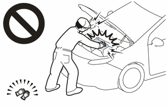
To prevent electric shock, wear insulated gloves when working on wire harnesses and components of the high voltage system.
- HINT:
-
When the cable is disconnected/reconnected to the auxiliary battery terminal, systems temporarily stop operating. However, each system has a function that completes learning the first time the system is used.
- ·
Learning completes when vehicle is driven
Effect/Inoperative Function When Necessary Procedures are not Performed Necessary Procedures Link Lane tracing assist system Drive the vehicle straight ahead at 35 km/h (22 mph) or more for 5 seconds or more. ( )
Pre-collision system Adaptive high beam system
- ·
Learning completes when vehicle is operated normally
Effect/Inoperative Function When Necessary Procedures are not Performed Necessary Procedures Link Air conditioning system After the ignition switch is turned to ON, the servo motor and expansion valve standard position is recognized. -
PROCEDURE

 1. PRECAUTION
|
|
Click here()
|
2. CAUTIONS FOR HIGH VOLTAGE SYSTEM COMPONENTS
|
|
Click here()
|
G3834
3.REMOVE SERVICE PLUG GRIP
53292A
4.REMOVE UPPER RADIATOR SUPPORT SEAL
53291B
5.REMOVE RADIATOR COVER PLATE
53295
6.REMOVE LOWER RADIATOR AIR DEFLECTOR
7.DRAIN COOLANT (for Inverter)
55708
8.REMOVE COWL TOP VENTILATOR LOUVER SUB-ASSEMBLY
1A906
9.REMOVE FC STACK COVER SUB-ASSEMBLY
G9200A
10.DISCONNECT FC CONVERTER POWER OUTLET CABLE (INVERTER WITH CONVERTER ASSEMBLY)
|
|
|
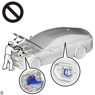
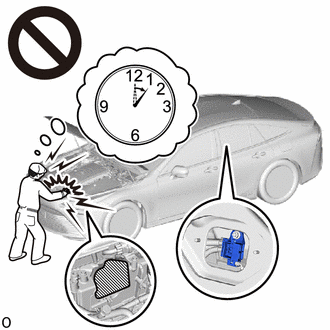
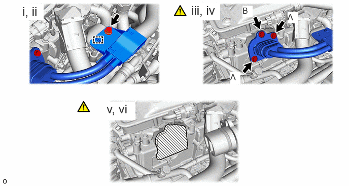
Remove the bolt.
Disengage the clamp.
Remove the 2 bolts A.
- NOTICE:
-
Removing the bolts in an incorrect order may damage the FC stack and FC converter power outlet cable (inverter with converter assembly).
Remove the bolt B.
- NOTICE:
- ·
Removing the bolts in an incorrect order may damage the FC stack and FC converter power outlet cable (inverter with converter assembly).
· 1.625,0.396 1.865,0.135 1.865,0.135 2.021,0.135 false 1.615,2.99 1.854,2.729 1.854,2.729 2.01,2.729 false 2.083,0.073 2.396,0.271 0.313,0.198 10 false *a 2.083,2.667 2.396,2.865 0.313,0.198 10 false *a
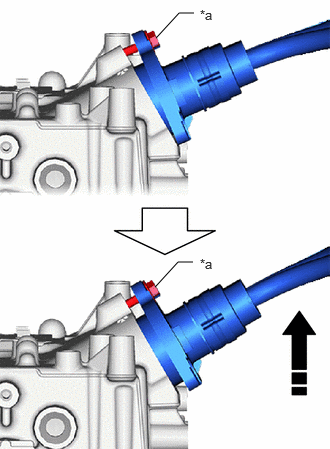
*a Bolt B 
Push The Cable
When removing bolt B, the connector will be tilted. If bolt B is removed with the connector tilted, the front holder may be removed and left in the stack. Therefore, push the cable from below so that the connector is not tilted while removing bolt B.
Disconnect the FC converter power outlet cable (inverter with converter assembly).
Protect the openings of the FC converter assembly with protective tape (non-residue type) to prevent the entry of foreign matter or water.
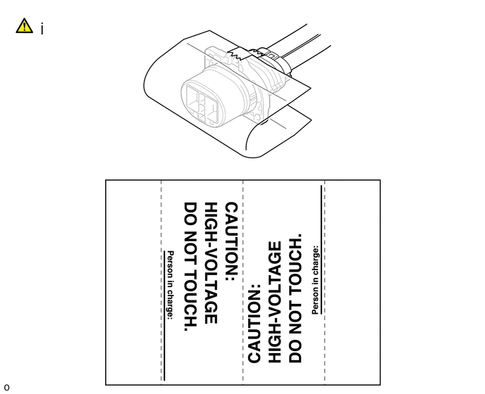
Use the "CAUTION: HIGH VOLTAGE DO NOT TOUCH" sign to notify other technicians that the high-voltage system is being inspected and/or repaired.
- NOTICE:
-
Be careful not to touch the terminal before or during attaching the display label.
If the FC converter power outlet front holder and FC converter power outlet front gasket are left in the stack, remove them using the following procedure.
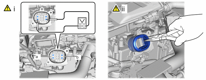
| *a | + Side | *b | - Side |
Check the voltage using the voltage detector hole.
- Standard Voltage:
0 V
- NOTICE:
-
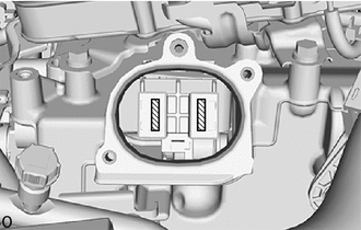 0,0 0,0 false

Terminal Contact Point
-
Do not touch the terminal contact point.
- HINT:
-
Use a measuring range of DC 750 V or more on the voltmeter.
Using needle-nose pliers with their tips wrapped with insulating tape, remove the FC converter power outlet front holder and FC converter power outlet front gasket .
- HINT:
-
When removing the FC converter power outlet front holder, pull it out straight up.
11.REMOVE CONNECTOR COVER ASSEMBLY
|
|
|
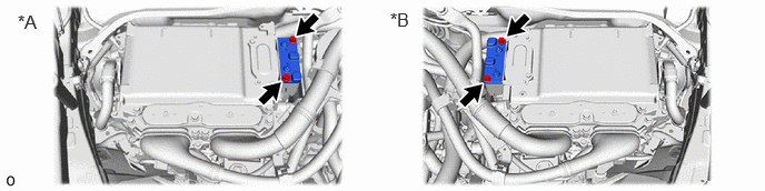
| *A | for LHD | *B | for RHD |
12.CHECK TERMINAL VOLTAGE
|
|
|
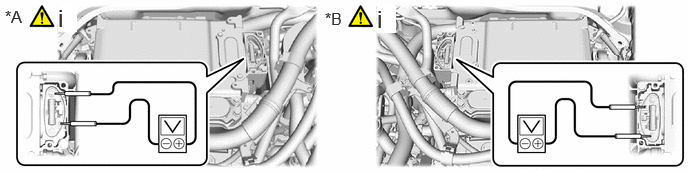
| *A | for LHD | *B | for RHD |
Using a voltmeter, measure the voltage between the terminals of the 2 phase connectors.
- Standard Voltage:
0 V
- HINT:
-
Use a measuring range of DC 750 V or more on the voltmeter.
13.TEMPORARILY INSTALL CONNECTOR COVER ASSEMBLY
|
|
|
| *A | for LHD | *B | for RHD |
G9223
14.REMOVE INVERTER TERMINAL COVER
|
|
|
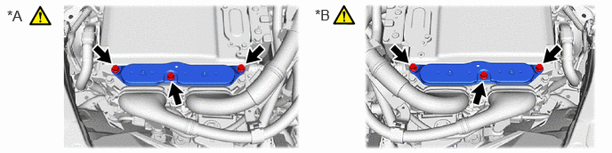
| *A | for LHD | *B | for RHD |
17A90
15.DISCONNECT FC AIR COMPRESSOR MOTOR CABLE ASSEMBLY
|
|
|
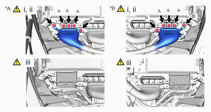
| *A | for LHD | *B | for RHD |
Using an insulated tool, remove the 3 bolts (A).
Using an insulated tool, remove the 2 bolts (B), and disconnect the FC air compressor motor cable assembly from the inverter with converter assembly.
- NOTICE:
- ·
Do not allow any foreign matter or water to enter the inverter with converter assembly.
·Do not touch the connector waterproofing rubber or terminals.
·Do not damage the terminals, connector housings or inverter with converter assembly during disconnection.
·Insulate the disconnected terminals with insulating tape.
·Cover the hole where the cable was connected with tape (non-residue type) or equivalent to prevent entry of foreign matter.
Protect the openings of the inverter with converter assembly with protective tape (non-residue type) to prevent the entry of foreign matter or water.
821H3B
16.DISCONNECT NO. 2 BATTERY PACK WIRE
|
|
|
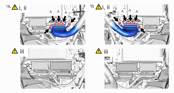
| *A | for LHD | *B | for RHD |
Using an insulated tool, remove the 3 bolts (A).
Using an insulated tool, remove the 2 bolts (B), and disconnect the No. 2 battery pack wire from the inverter with converter assembly.
- NOTICE:
- ·
Do not allow any foreign matter or water to enter the inverter with converter assembly.
·Do not touch the connector waterproofing rubber or terminals.
·Do not damage the terminals, connector housings or inverter with converter assembly during disconnection.
·Insulate the disconnected terminals with insulating tape.
·Cover the hole where the cable was connected with tape (non-residue type) or equivalent to prevent entry of foreign matter.
Protect the openings of the inverter with converter assembly with protective tape (non-residue type) to prevent the entry of foreign matter or water.
G1240C
17.REMOVE INVERTER MOTOR CABLE BRACKET ASSEMBLY
|
|
|
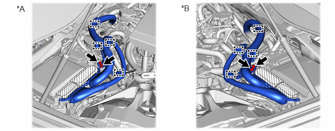
| *A | for LHD | *B | for RHD |
G9200A
18.DISCONNECT FC CONVERTER POWER OUTLET CABLE (INVERTER WITH CONVERTER ASSEMBLY)
|
|
|
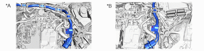
| *A | for LHD | *B | for RHD |
53705F
19.REMOVE FENDER APRON BRACE SUB-ASSEMBLY RH (for LHD)

53706A
20.REMOVE FENDER APRON BRACE SUB-ASSEMBLY LH (for RHD)

G90A1
21.DISCONNECT NO. 1 FC INVERTER COOLING HOSE SUB-ASSEMBLY
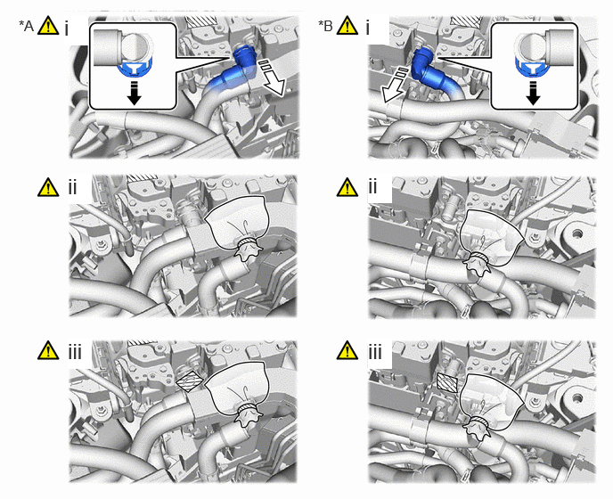
| *A | for LHD | *B | for RHD |
Release the retainer and disconnect the No. 1 FC inverter cooling hose sub-assembly from the inverter with converter assembly as shown in the illustration.
Protect the connecting part of the No. 1 FC inverter cooling hose sub-assembly with a plastic bag to prevent entry of foreign matter.
Protect the openings of the inverter with converter assembly with protective tape (non-residue type) to prevent the entry of foreign matter or water.
- NOTICE:
-
Apply insulating tape to the pipes and in the disconnected hoses, or cover the pipes and hoses with plastic bags to prevent foreign matter from entering the cooling system and to prevent coolant from spilling near the inverter with converter assembly.
G91C3
22.DISCONNECT NO. 3 FC INVERTER COOLING HOSE
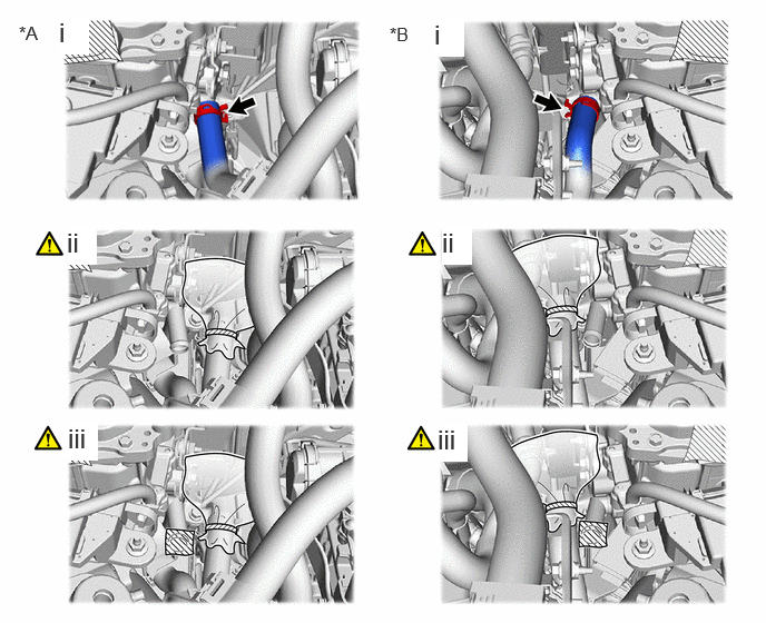
| *A | for LHD | *B | for RHD |
Release the hose clip and disconnect the No. 3 FC inverter cooling hose from the inverter with converter assembly as shown in the illustration.
Protect the connecting part of the No. 3 FC inverter cooling hose with a plastic bag to prevent entry of foreign matter.
Protect the openings of the inverter with converter assembly with protective tape (non-residue type) to prevent the entry of foreign matter or water.
- NOTICE:
-
Apply insulating tape to the pipes and in the disconnected hoses, or cover the pipes and hoses with plastic bags to prevent foreign matter from entering the cooling system and to prevent coolant from spilling near the inverter with converter assembly.
G9205A
23.DISCONNECT INVERTER BUS-BAR PLATE SUB-ASSEMBLY
|
|
|
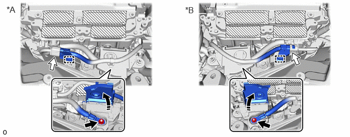
| *A | for LHD | *B | for RHD |
87209C
24.REMOVE WATER HOSE SUB-ASSEMBLY C (for RHD)

25.REMOVE WIRE HARNESS CLAMP BRACKET
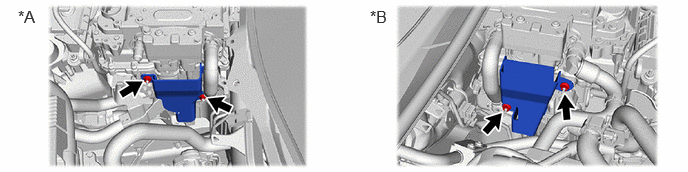
| *A | for LHD | *B | for RHD |
82111C
26.DISCONNECT FRONT COMPARTMENT MAIN WIRE
|
|
|
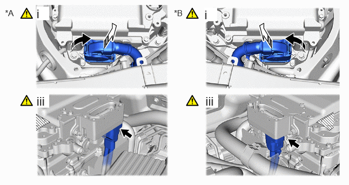
| *A | for LHD | *B | for RHD |
Raise the lock lever and disconnect the front compartment main wire from the inverter with converter assembly as shown in the illustration.
- NOTICE:
- ·
Insulate the disconnected connector with insulating tape.
·Cover the hole where the connector was connected with tape (non-residue type) or equivalent to prevent entry of foreign matter.
Remove the connector cover assembly.
Click hereEngine / Hybrid System>HYBRID / BATTERY CONTROL>INVERTER WITH CONVERTER>REMOVAL
Disconnect the front compartment main wire from the inverter with converter assembly.
- NOTICE:
- ·
Do not allow any foreign matter or water to enter the inverter with converter assembly.
·Do not touch the connector waterproofing rubber or terminals.
·Do not damage the connectors, connector housings or inverter with converter assembly during disconnection.
·Insulate the disconnected terminals with insulating tape.
·Cover the hole where the cable was connected with tape (non-residue type) or equivalent to prevent entry of foreign matter.
Temporarily install the connector cover assembly.
Click hereEngine / Hybrid System>HYBRID / BATTERY CONTROL>INVERTER WITH CONVERTER>REMOVAL
G9A2C
27.REMOVE FC JUNCTION CABLE
|
|
|
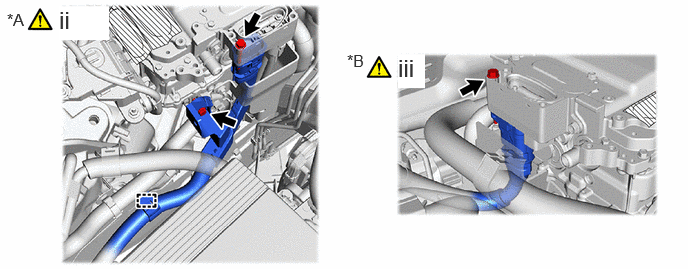
| *A | for LHD | *B | for RHD |
Remove the connector cover assembly.
Click hereEngine / Hybrid System>HYBRID / BATTERY CONTROL>INVERTER WITH CONVERTER>REMOVAL
for LHD:
Remove the 2 bolts and disengage the clamp, and disconnect the FC junction cable from the inverter with converter assembly.
- NOTICE:
- ·
Do not allow any foreign matter or water to enter the inverter with converter assembly.
·Do not touch the connector waterproofing rubber or terminals.
·Do not damage the connectors, connector housings or inverter with converter assembly during disconnection.
·Insulate the disconnected terminals with insulating tape.
·Cover the hole where the cable was connected with tape (non-residue type) or equivalent to prevent entry of foreign matter.
for RHD:
Remove the bolt, and disconnect the FC junction cable from the inverter with converter assembly.
- NOTICE:
- ·
Do not allow any foreign matter or water to enter the inverter with converter assembly.
·Do not touch the connector waterproofing rubber or terminals.
·Do not damage the connectors, connector housings or inverter with converter assembly during disconnection.
·Insulate the disconnected terminals with insulating tape.
·Cover the hole where the cable was connected with tape (non-residue type) or equivalent to prevent entry of foreign matter.
Temporarily install the connector cover assembly.
Click hereEngine / Hybrid System>HYBRID / BATTERY CONTROL>INVERTER WITH CONVERTER>REMOVAL
G9200A
28.REMOVE INVERTER WITH CONVERTER ASSEMBLY
|
|
|
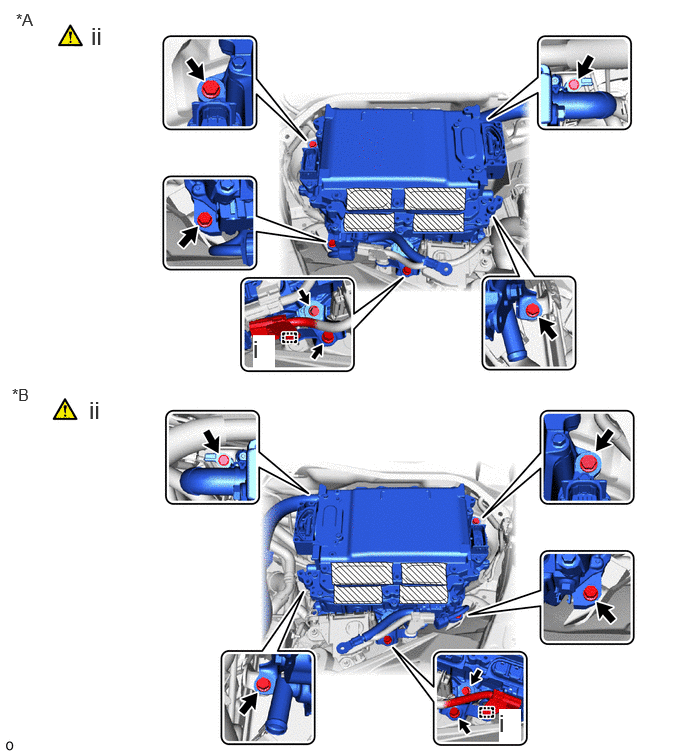
| *A | for LHD | *B | for RHD |
Disengage the clamp from the No. 6 inverter bracket.
Remove the 6 bolts, No. 6 inverter bracket and inverter with converter assembly.
- NOTICE:
- ·
Since the inverter with converter assembly is very heavy, 2 people are needed to remove the inverter with converter assembly. When removing the inverter with converter assembly, do not damage the parts around it.
·To prevent damage, do not hold the inverter with converter assembly by the connectors.
·To prevent damage due to static electricity, do not touch the terminals of the disconnected connectors.
·Cover the connectors with insulating tape to prevent foreign matter or water from entering.
- HINT:
-
Even after the coolant is drained, coolant remains in the inverter due to its internal structure. Therefore, seal or cover the pipes when removing the inverter so that coolant does not spill out.
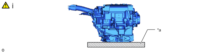
| *a | Cushion | - | - |
When removing and storing the inverter with converter assembly, make sure to install the inverter terminal cover and place a cushion under the inverter with converter assembly to protect it.
- NOTICE:
-
Do not place the inverter with converter assembly upside down.
G9217A
29.REMOVE NO. 4 INVERTER BRACKET
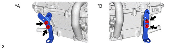
| *A | for LHD | *B | for RHD |
G9205A
30.REMOVE INVERTER BUS-BAR PLATE SUB-ASSEMBLY
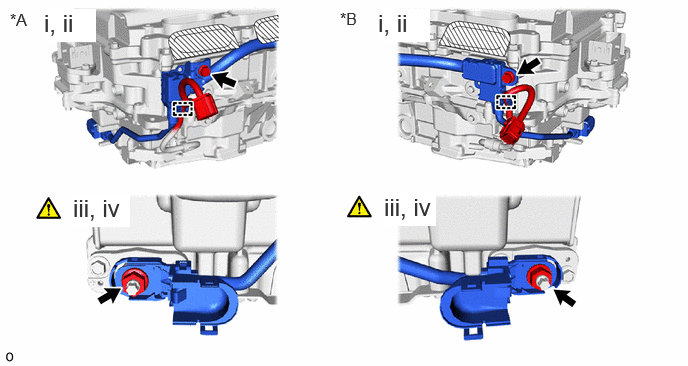
| *A | for LHD | *B | for RHD |
Disengage the clamp and remove the bolt.
Open the terminal cover.
Remove the nut.
- NOTICE:
-
If the stud bolt becomes loose when removing the nut, tighten the stud bolt to a torque of 10 N*m (102 kgf*cm 7 ft.*lbf).
Remove the inverter bus-bar plate sub-assembly.
- NOTICE:
-
If the inverter bus-bar plate sub-assembly is dropped or deformed, replace it with a new one.
31.REMOVE NO. 1 INVERTER COOLING HOSE
|
|
|
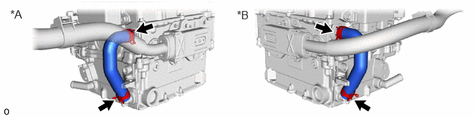
| *A | for LHD | *B | for RHD |
32.REMOVE HIGH VOLTAGE FUSE
|
|
|
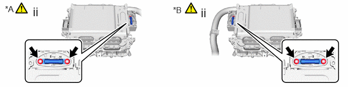
| *A | for LHD | *B | for RHD |
Remove the connector cover assembly.
Click hereEngine / Hybrid System>HYBRID / BATTERY CONTROL>INVERTER WITH CONVERTER>REMOVAL
Remove the 2 nuts and high voltage fuse.
- NOTICE:
-
Do not allow any foreign matter or water to enter the inverter with converter assembly.
Temporarily install the connector cover assembly.
Click hereEngine / Hybrid System>HYBRID / BATTERY CONTROL>INVERTER WITH CONVERTER>REMOVAL