HYBRID / BATTERY CONTROL HYBRID CONTROL SYSTEM Drive Mode Select Switch Circuit
DESCRIPTION
When the DRIVE MODE switch (No. 1 pattern select switch assembly) is operated, a switch signal is sent to the EV control ECU and the EV control ECU changes the drive mode (SPORT, NORMAL, ECO).
WIRING DIAGRAM
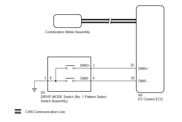
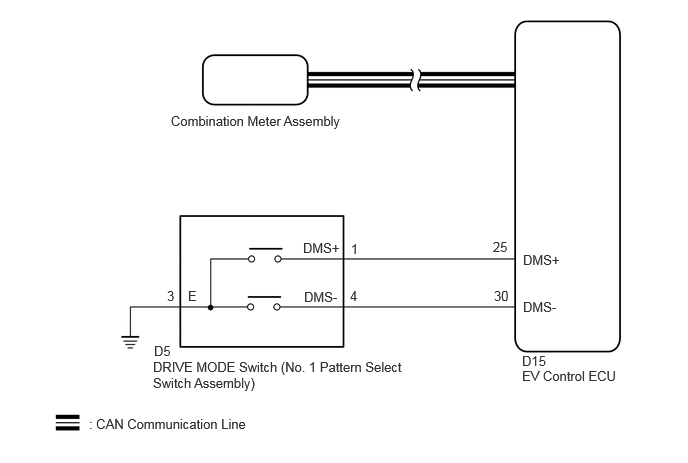
PROCEDURE
Enter the following menus: System Select / CAN Bus Check.
- CAN Bus Check
- 50007
- Result:
Result Proceed to All of the ECUs and sensors that are currently connected to the CAN communication system are displayed A None of the ECUs and sensors that are currently connected to the CAN communication system are displayed, or some of them are not displayed B
A
B
Click herePower Source / Network>NETWORKING>CAN COMMUNICATION SYSTEM>HOW TO PROCEED WITH TROUBLESHOOTING
Enter the following menus: System Select / Health Check.
Check for DTCs.
- Result:
Result Proceed to No DTCs are output. A DTCs are output. B
Turn the ignition switch off.
A
B
Turn the ignition switch to ON.
Operate the DRIVE MODE switch (No. 1 pattern select switch assembly) to change the drive mode.
Check that the drive mode indicator is displayed on the multi-information display and changes according to the selected drive mode.
- Result:
Result Proceed to The display changes according to the DRIVE MODE switch operation A The display does not change according to the DRIVE MODE switch operation B
Turn the ignition switch off.
A
Click hereEngine / Hybrid System>HYBRID / BATTERY CONTROL>HYBRID CONTROL SYSTEM>PROBLEM SYMPTOMS TABLE
B
Read the value displayed on the GTS.
- Powertrain > EV > Data List
-
Tester Display Drive Mode Switch- Drive Mode Switch+ - 50003 397 640,641
- Result:
Result Proceed to The display changes according to the DRIVE MODE switch operation A Other than above B
Turn the ignition switch off.
A
Click hereVehicle Interior>METER / GAUGE / DISPLAY>METER / GAUGE SYSTEM>HOW TO PROCEED WITH TROUBLESHOOTING
B
Click hereDrivetrain>Q710 (HYBRID TRANSMISSION / TRANSAXLE)>PATTERN SELECT SWITCH>INSPECTION
- Result:
Proceed to OK NG
OK
NG
Disconnect the D5 DRIVE MODE switch (NO. 1 pattern select switch assembly) connector.
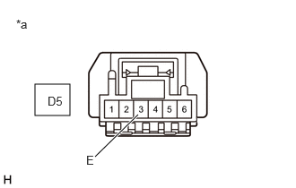
| *a | Front view of wire harness connector
(to DRIVE MODE Switch (NO. 1 Pattern Select switch Assembly)) |
Measure the resistance according to the value(s) in the table below.
- Standard Resistance:
Tester Connection Condition Specified Condition Click Location & Routing(D5)Location & Routingewd_type=routing;type=c;code=D5
Click Connector(D5)Instrument Panel>Instrument Panel Wire>No. 1 Pattern Select Switch Assemblyewd_type=component;type=c;code=D5;pinno=3
D5-3 (E) - Body ground Always Below 1 Ω
- Result:
Proceed to OK NG
Reconnect the D5 DRIVE MODE switch (NO. 1 pattern select switch assembly) connector.
OK
NG
Disconnect the A8*1 or D15*2 EV control ECU connector.
*1: for LHD
*2: for RHD
Disconnect the D5 DRIVE MODE switch (NO. 1 pattern select switch assembly) connector.
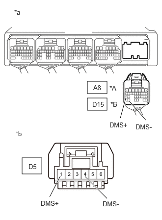
| *A | for LHD |
| *B | for RHD |
| *a | Rear view of wire harness connector
(to EV Control ECU) |
| *b | Front view of wire harness connector
(to DRIVE MODE Switch (NO. 1 Pattern Select Switch Assembly)) |
Measure the resistance according to the value(s) in the table below.
- Standard Resistance:
for LHD: Tester Connection Condition Specified Condition Click Location & Routing(A8,D5)Location & Routingewd_type=routing;type=c,c;code=A8,D5
Click Connector(A8)Instrument Panel>Front Compartment Main Wire>EV Control ECUewd_type=component;type=c;code=A8;pinno=30,25
Click Connector(D5)Instrument Panel>Instrument Panel Wire>No. 1 Pattern Select Switch Assemblyewd_type=component;type=c;code=D5;pinno=4,1
A8-30 (DMS-) - D5-4 (DMS-) Always Below 1 Ω A8-25 (DMS+) - D5-1 (DMS+) Always Below 1 Ω A8-30 (DMS-) or D5-4 (DMS-) - Body ground Always 10 kΩ or higher A8-25 (DMS+) or D5-1 (DMS+) - Body ground Always 10 kΩ or higher
for RHD: Tester Connection Condition Specified Condition Click Location & Routing(D15,D5)Location & Routingewd_type=routing;type=c,c;code=D15,D5
Click Connector(D15)Instrument Panel>Instrument Panel Wire>EV Control ECUewd_type=component;type=c;code=D15;pinno=30,25
Click Connector(D5)Instrument Panel>Instrument Panel Wire>No. 1 Pattern Select Switch Assemblyewd_type=component;type=c;code=D5;pinno=4,1
D15-30 (DMS-) - D5-4 (DMS-) Always Below 1 Ω D15-25 (DMS+) - D5-1 (DMS+) Always Below 1 Ω D15-30 (DMS-) or D5-4 (DMS-) - Body ground Always 10 kΩ or higher D15-25 (DMS+) or D5-1 (DMS+) - Body ground Always 10 kΩ or higher
- Result:
Proceed to OK NG
Reconnect the D5 DRIVE MODE switch (NO. 1 pattern select switch assembly) connector.
Reconnect the A8*1 or D15*2 EV control ECU connector.
*1: for LHD
*2: for RHD
OK
NG