FC CONTROL HYDROGEN INJECTOR INSTALLATION
CAUTION / NOTICE / HINT
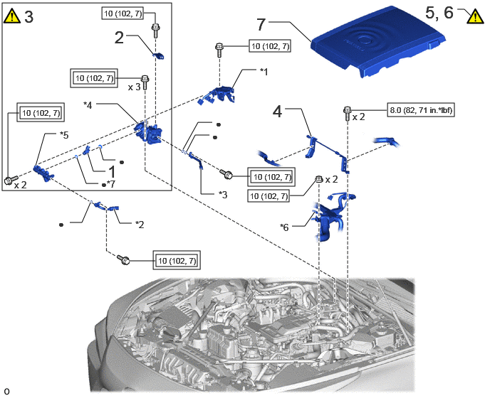
| Procedure | Part Name Code | 
|

|

|
|
|---|---|---|---|---|---|
| 1 | FUEL INJECTOR ASSEMBLY | 23250H | - | - | - |
| 2 | WIRE HARNESS CLAMP BRACKET | - | - | - | - |
| 3 | HYDROGEN SUPPLY PRESSURE REGULATOR ASSEMBLY | 23A30 | ( ) |
- | - |
| 4 | FC STACK COVER BRACKET | 1A911 | - | - | |
| 5 | INSPECT FOR HYDROGEN GAS LEAK (for Medium Pressure) | - | ()
|
- | - |
| 6 | INSPECT FOR HYDROGEN GAS LEAK (for Low Pressure) | - | ()
|
- | - |
| 7 | FC STACK COVER SUB-ASSEMBLY | 1A906 | - | - | - |
| *1 | NO. 1 HYDROGEN DETECTOR BRACKET | *2 | NO. 1 HYDROGEN TUBE |
| *3 | NO. 1 HYDROGEN SUPPLY TUBE SUB-ASSEMBLY | *4 | HYDROGEN SUPPLY PRIMARY PIPE SUB-ASSEMBLY |
| *5 | HYDROGEN SUPPLY SECONDARY PIPE SUB-ASSEMBLY | *6 | WIRE HARNESS |
| *7 | INSULATOR | - | - |

|
Tightening torque for "Major areas involving basic vehicle performance such as moving/turning/stopping": N*m (kgf*cm, ft.*lbf) | 
|
N*m (kgf*cm, ft.*lbf): Specified torque |
| ● | Non-reusable part | - | - |
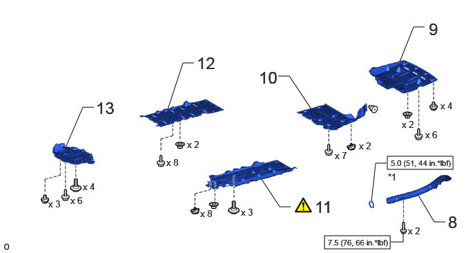
| Procedure | Part Name Code |
|
|
|
|
|---|---|---|---|---|---|
| 8 | NO. 3 FC EXHAUST PIPE | 17DB3 | - | - | - |
| 9 | NO. 1 FLOOR UNDER COVER | 58398F | - | - | - |
| 10 | REAR FLOOR SIDE MEMBER COVER LH | 57628E | - | - | - |
| 11 | NO. 2 FLOOR BOARD SUB-ASSEMBLY | 58402K | ()
|
- | - |
| 12 | REAR NO. 3 FLOOR BOARD SUB-ASSEMBLY | 58403L | - | - | - |
| 13 | REAR NO. 4 FLOOR BOARD SUB-ASSEMBLY | 58404B | - | - | - |
| *1 | HOSE CLAMP | - | - |
|
|
N*m (kgf*cm, ft.*lbf): Specified torque | - | - |
PROCEDURE

 23250H
1.INSTALL FUEL INJECTOR ASSEMBLY
- Torque:
- 10 N*m (102 kgf*cm, 7 ft.*lbf)
2.INSTALL WIRE HARNESS CLAMP BRACKET
- Torque:
- 10 N*m (102 kgf*cm, 7 ft.*lbf)
23A30
3.INSTALL HYDROGEN SUPPLY PRESSURE REGULATOR ASSEMBLY
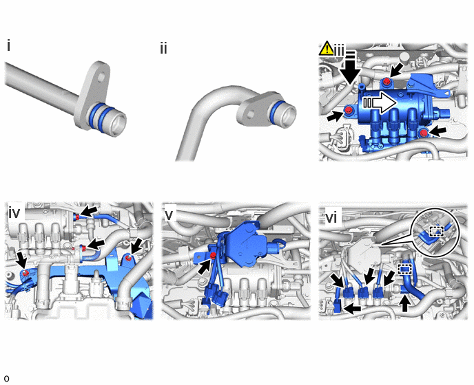

|
Pull down | 
|
Shift |
Install the new O-ring to the No. 1 hydrogen supply tube sub-assembly.
Install the new O-ring to the No. 1 hydrogen tube.
Connect the No. 1 hydrogen tube and No. 1 hydrogen supply tube sub-assembly to the hydrogen supply puressure regulator assembly and install the hydrogen supply puressure regulator assembly with the 3 bolts.
- Torque:
- 10 N*m (102 kgf*cm, 7 ft.*lbf)
Install the 2 bolts and 2 nuts.
- Torque:
- 10 N*m (102 kgf*cm, 7 ft.*lbf)
Connect the No. 1 hydrogen detector bracket with the bolt.
- Torque:
- 10 N・m (102 kgf・cm, )
Connect the 5 connectors and attach the 2 clamps.
1A911
4.INSTALL FC STACK COVER BRACKET
- Torque:
- 8.0 N*m (82 kgf*cm, 71 in.*lbf)
5.INSPECT FOR HYDROGEN GAS LEAK (for Medium Pressure)
- HINT:
-
Use the GTS, perform a hydrogen leak inspection when replacing or removing and installing medium-pressure hydrogen-replated parts (medium pressure port of hydrogen supply regulator, hydrogen primary pressure sensor and fuel injector), and removing and installing medium-pressure hydrogen-related piping (No. 1 hydrogen supply tube, No. 2 hydrogen supply tube, and No. 3 hydrogen supply tube).
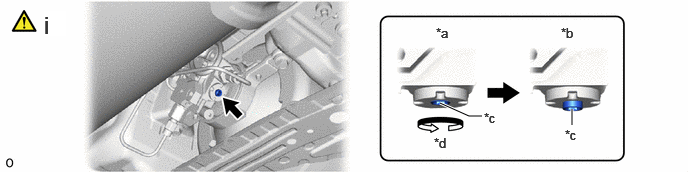
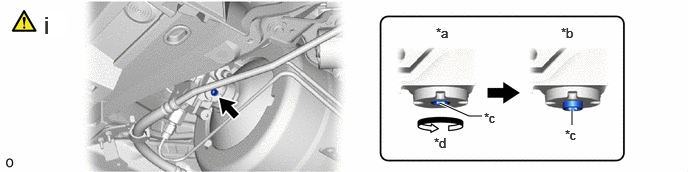
| *a | Manual Valve Closed | *b | Manual Valve Open |
| *c | Adjustment Bolt | *d | Counterclockwise |
Using an 8 mm socket hexagon wrench, rotate the adjustment bolt counterclockwise, and open the No. 1 hydrogen tank assembly manual valve.
- NOTICE:
- ·
The manual valve shuts off the pressure from the hydrogen tank assembly, so be careful not to damage the hexagonal portion.
·If the hexagonal portion is damaged, it will be impossible to operate the adjustment bolt.
·Do not rotate the adjustment bolt more than 4 rotations.
·Rotating the adjustment bolt more than 4 rotations could damage the manual valve.
·If the manual valve is damaged, it will be necessary to replace the No. 1 hydrogen tank assembly.
- HINT:
-
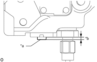 0.917,1.625 1.094,1.625 1.094,1.625 1.448,1.385 false 0.719,1.531 1.031,1.688 0.313,0.156 10 false *a 3.021,1.271 3.25,1.427 0.229,0.156 10 false *b
*a Adjustment Bolt *b Protrusion
-
When the manual valve is opened, the protrusion of the adjustment bolt is 3.5 mm (0.138 in.) or less.
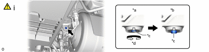
| *a | Manual Valve Closed | *b | Manual Valve Open |
| *c | Adjustment Bolt | *d | Counterclockwise |
Using an 8 mm socket hexagon wrench, rotate the adjustment bolt counterclockwise, and open the No. 2 hydrogen tank assembly manual valve.
- NOTICE:
- ·
The manual valve shuts off the pressure from the hydrogen tank assembly, so be careful not to damage the hexagonal portion.
·If the hexagonal portion is damaged, it will be impossible to operate the adjustment bolt.
·Do not rotate the adjustment bolt more than 4 rotations.
·Rotating the adjustment bolt more than 4 rotations could damage the manual valve.
·If the manual valve is damaged, it will be necessary to replace the No. 2 hydrogen tank assembly.
- HINT:
-
0.917,1.625 1.094,1.625 1.094,1.625 1.448,1.385 false 0.719,1.531 1.031,1.688 0.313,0.156 10 false *a 3.021,1.271 3.25,1.427 0.229,0.156 10 false *b
*a Adjustment Bolt *b Protrusion
-
When the manual valve is opened, the protrusion of the adjustment bolt is 3.5 mm (0.138 in.) or less.
| *a | Manual Valve Closed | *b | Manual Valve Open |
| *c | Adjustment Bolt | *d | Counterclockwise |
Using an 8 mm socket hexagon wrench, rotate the adjustment bolt counterclockwise, and open the No. 3 hydrogen tank assembly manual valve.
- NOTICE:
- ·
The manual valve shuts off the pressure from the hydrogen tank assembly, so be careful not to damage the hexagonal portion.
·If the hexagonal portion is damaged, it will be impossible to operate the adjustment bolt.
·Do not rotate the adjustment bolt more than 4 rotations.
·Rotating the adjustment bolt more than 4 rotations could damage the manual valve.
·If the manual valve is damaged, it will be necessary to replace the No. 3 hydrogen tank assembly.
- HINT:
-
0.917,1.625 1.094,1.625 1.094,1.625 1.448,1.385 false 0.719,1.531 1.031,1.688 0.313,0.156 10 false *a 3.021,1.271 3.25,1.427 0.229,0.156 10 false *b
*a Adjustment Bolt *b Protrusion
-
When the manual valve is opened, the protrusion of the adjustment bolt is 3.5 mm (0.138 in.) or less.
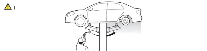
Blow compressed air around the front compartment room and underside of the vehicle.
- HINT:
-
To enable accurate detection of hydrogen gas leaks from the piping, blow compressed air from the front of the vehicle towards the rear.
Connect the GTS to the DLC3.
Turn the ignition switch on (IG).
Enter the following menus: Powertrain / EV / Utility / Leak Check
- Powertrain > EV > Utility
-
Tester Display Leak Check - 50005 397 5671

Following the display on the GTS, check for hydrogen gas leaks.

Select mid-high pressure point leak check.

Using SST and a hydrogen gas detector, perform measurements for approximately 10 seconds at the locations where components were removed and installed during the replacement of components.
- SST
- 09401-62020
- NOTICE:
- ·
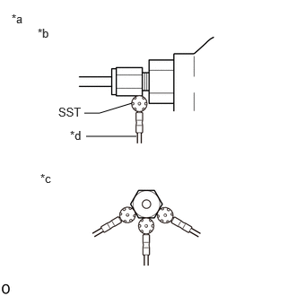 1.531,1.198 1.156,1.313 1.156,1.313 0.979,1.313 false 1,1.583 1.583,1.583 false 0.438,0.302 0.75,0.458 0.313,0.156 10 false *b 0.469,1.99 0.781,2.146 0.313,0.156 10 false *c 0.677,1.219 0.99,1.375 0.313,0.156 10 false SST 0.813,1.49 1,1.646 0.188,0.156 10 false *d 0.135,0.135 0.448,0.292 0.313,0.156 10 false *a
*a Hydrogen Gas Detector Contact Location and Direction *b Side View *c Cutaway View *d Hydrogen Gas Detector
To perform the measurement, hold the tip of the hydrogen gas detector as shown in the illustration (*c), in contact with a single location from any one of the directions shown.
·Hold the tip in light contact with the location so that the tip does not deform.
- HINT:
- ·
Immediately after the measurement starts, the measured value may be unstable.
·If the measured value is outside of the specification, replace the leaking component with a new one.
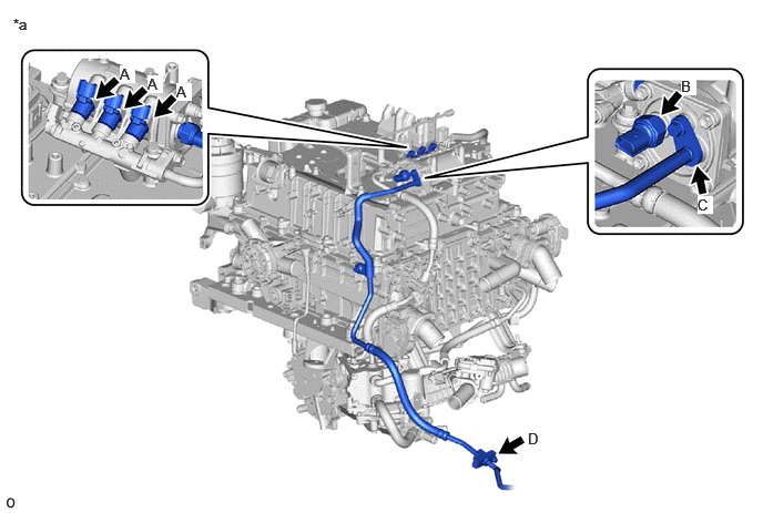
| *a | FC Stack-side Measurement Location | - | - |
| Illustration Item | Measurement Location | Measurement Method | Specified Value |
|---|---|---|---|
| A | Connection between Hydrogen Supply Primary Pipe Sub-assembly x Fuel Injector Assembly | Measure the area area around the connection. | Less than 500ppm |
| B | Connection between Hydrogen Primary Pressure Sensor x Hydrogen Supply Primary Pipe Sub-assembly | ||
| C | Connection between No. 1 Hydrogen Supply Tube x Hydrogen Supply Primary Pipe Sub-assembly | ||
| D | Connection between No. 1 Hydrogen Supply Tube x No. 2 Hydrogen Supply tube |
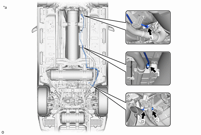
| *a | Hydrogen Tank-side Measurement Location | - | - |
| Illustration Item | Measurement Location | Measurement Method | Specified Value |
|---|---|---|---|
|
*1: If the value is not as specified, replace the O-ring of the medium pressure port. |
|||
| A | Connection between No. 1 Hydrogen Supply Tube x No. 2 Hydrogen Supply Tube | Measure the area area around the connection. | Less than 500ppm |
| B | Connection between No. 2 Hydrogen Supply Tube Sub-assembly and No. 3 Hydrogen Supply Tube Sub-assembly | ||
| C | Medium Pressure Port of Hydrogen Supply Regulator
*1 |
||
| D | Connection between No. 3 Hydrogen Supply Tube Sub-assembly and Hydrogen Supply Regulator | ||

The check for hydrogen gas leaks (for medium pressure) is complete.
6.INSPECT FOR HYDROGEN GAS LEAK (for Low Pressure)
|
|
|
- HINT:
-
Use the GTS, perform a hydrogen leak inspection when replacing or removing and installing low-pressure hydrogen- elated parts (fuel injector assembly, hydrogen secondary pressure sensor, hydrogen recirculation pump assembly, hydrogen recirculation separator assembly, and FC stack assembly, FC converter assembly), and removing and installing low-pressure hydrogen-related piping (No. 1 hydrogen tube, No. 2 hydrogen tube, and No. 3 hydrogen tube).
Blow compressed air around the front compartment room and underside of the vehicle.
- HINT:
-
To enable accurate detection of hydrogen gas leaks from the piping, blow compressed air from the front of the vehicle towards the rear.
Connect the GTS to the DLC3.
Turn the ignition switch on (IG).
Enter the following menus: Powertrain / EV / Utility / Leak Check
- Powertrain > EV > Utility
-
Tester Display Leak Check - 50005 397 5671
Following the display on the GTS, check for hydrogen gas leaks.

Select low pressure point leak check.
Using SST and a hydrogen gas detector, perform measurements for approximately 10 seconds at the locations where components were removed and installed during the replacement of components.
- SST
- 09401-62020
- NOTICE:
- ·
1.531,1.198 1.156,1.313 1.156,1.313 0.979,1.313 false 1,1.583 1.583,1.583 false 0.438,0.302 0.75,0.458 0.313,0.156 10 false *b 0.469,1.99 0.781,2.146 0.313,0.156 10 false *c 0.677,1.219 0.99,1.375 0.313,0.156 10 false SST 0.813,1.49 1,1.646 0.188,0.156 10 false *d 0.135,0.135 0.448,0.292 0.313,0.156 10 false *a
*a Hydrogen Gas Detector Contact Location and Direction *b Side View *c Cutaway View *d Hydrogen Gas Detector
To perform the measurement, hold the tip of the hydrogen gas detector as shown in the illustration (*c), in contact with a single location from any one of the directions shown.
·Hold the tip in light contact with the location so that the tip does not deform.
- HINT:
- ·
Immediately after the measurement starts, the measured value may be unstable.
·If the measured value is outside of the specification, replace the leaking component with a new one.
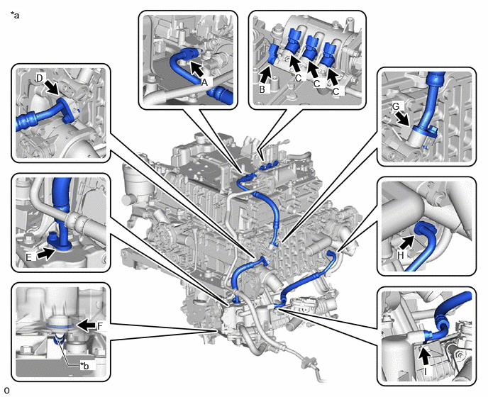
| *a | Measurement Locations | *b | Insertion Slot |
| Illustration Item | Measurement Location | Measurement Method | Specified Value |
|---|---|---|---|
| A | Connection between No. 1 Hydrogen Tube x Hydrogen supply Secondary Pipe Sub-assembly | Measure the area near the piping, connecting portion, or sensor connecting portion. | Less than 500ppm |
| B | Connection between Hydrogen Secondary Pressure Sensor x Hydrogen Supply Secondary Pipe Sub-assembly | ||
| C | Connection between Fuel Injector Assembly x Hydrogen Supply Secondary Pipe Sub-assembly | ||
| D | Connection between No. 2 Hydrogen Tube x FC Stack Hydrogen Inlet | ||
| E | Connection between No. 2 Hydrogen Tube x Hydrogen Recirculation Pump Assembly | ||
| F | Connection between Hydrogen Recirculation Pump Assembly x Hydrogen Recirculation Separator Assembly | Remove SST (hydrogen gas detector adapter) and insert the hydrogen gas detector probe into the insertion slot to perform a measurement. | |
| G | Connection between No. 1 Hydrogen Tube x FC Stack Hydrogen Inlet | Measure the area near the piping, connecting portion, or sensor connecting portion. | |
| H | Connection between No. 3 Hydrogen Tube x FC Stack Assembly | ||
| I | Connection between No. 3 Hydrogen Tube x Hydrogen Recirculation Separator Assembly |

Perform the end processing, the check for hydrogen gas leaks (for low pressure) is complete.
1A906
7.INSTALL FC STACK COVER SUB-ASSEMBLY
17DB3
8.INSTALL NO. 3 FC EXHAUST PIPE
58398F
9.INSTALL NO. 1 FLOOR UNDER COVER
57628E
10.INSTALL REAR FLOOR SIDE MEMBER COVER LH
58402K
11.INSTALL NO. 2 FLOOR BOARD SUB-ASSEMBLY
|
|
Click here()
|
58403L
12.INSTALL REAR NO. 3 FLOOR BOARD SUB-ASSEMBLY
58404B
13.INSTALL REAR NO. 4 FLOOR BOARD SUB-ASSEMBLY