HEATING / AIR CONDITIONING AIR CONDITIONING SYSTEM P1F0A High Voltage Electric Heater Circuit
DESCRIPTION
The air conditioning amplifier assembly uses the target blower temperature to calculate the target water temperature, and selects the electric heater sub-assembly drive level based on the water temperature sensor value.
The air conditioning amplifier assembly sends the drive level to the EV control ECU via the CAN communication system, and the EV control ECU drives the electric heater sub-assembly.
| DTC No. | Detection Item | DTC Detection Condition | Trouble Area | Memory | DTC Output from | Priority |
|---|---|---|---|---|---|---|
| P1F0A | High Voltage Electric Heater Circuit | The air conditioning amplifier assembly stores this DTC if it detects a malfunction in the electric heater sub-assembly.
Diagnosis condition:
When electric heater sub-assembly is driven Malfunction status:
Even if electric heater sub-assembly drive signal is output, but electric heater sub-assembly is not driven or malfunction Detection time:
Detects malfunction signal for 10 seconds or more |
·
EV control system ·
Harness or connector ·
EV control ECU ·
Electric heater sub-assembly |
Memorized | Air Conditioner | A |
WIRING DIAGRAM
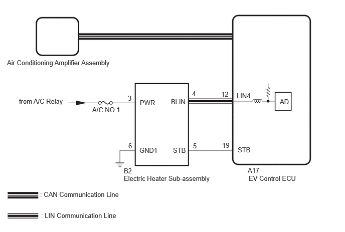
CAUTION / NOTICE / HINT
- CAUTION:
- ·
After removing the EV battery service plug grip and FC converter power outlet cable (inverter with converter assembly) on FC converter side, store them according to the following guidelines to prevent other technicians from accidentally reconnecting them while work is being performed on the high voltage systems.
·After removing the EV battery service plug grip and FC converter power outlet cable (inverter with converter assembly) on FC converter side, wait for at least 10 minutes before touching any of the high-voltage connectors or terminals. After waiting for 10 minutes, check the voltage at the terminals in the inspection point in the inverter with converter assembly. The voltage should be 0 V before beginning work.
- NOTICE:
- ·
Inspect the fuses for circuits related to this system before performing the following procedure.
·After the ignition switch is turned off, there may be a waiting time before disconnecting the negative (-) auxiliary battery terminal.
Click hereGeneral>SETUP>WHEN DISCONNECTING OR RECONNECTING BATTERY TERMINAL>BEFORE DISCONNECTING BATTERY
·When disconnecting and reconnecting the auxiliary battery
Click hereGeneral>SETUP>WHEN DISCONNECTING OR RECONNECTING BATTERY TERMINAL>WORK PROCEDURE
- HINT:
-
When disconnecting and reconnecting the auxiliary battery, there is an automatic learning function that completes learning when the respective system is used.
-
Click hereGeneral>SETUP>WHEN DISCONNECTING OR RECONNECTING BATTERY TERMINAL>AUTOMATIC LEARNING CHART
·The hybrid control system and air conditioning system output DTCs separately. Perform troubleshooting for the hybrid control system first if DTCs from these systems are output simultaneously.
PROCEDURE
- CAUTION:
-
Do not disconnect the connector on the high-voltage side.
Pre-procedure1
Disconnect the B2 electric heater sub-assembly connector.
Procedure1
Measure the resistance according to the value(s) in the table below.
- Standard Resistance:
Tester Connection Condition Specified Condition Click Location & Routing(B2)Location & Routingewd_type=routing;type=c;code=B2
Click Connector(B2)Engine Compartment>No. 2 Stack Wire>Electric Heater Sub-Assemblyewd_type=component;type=c;code=B2;pinno=6
B2-6 (GND1) - Body ground Always Below 1 Ω
- Result:
Proceed to OK NG
Post-procedure1
None
OK
NG
- CAUTION:
-
Do not disconnect the connector on the high-voltage side.
Pre-procedure1
Disconnect the B2 electric heater sub-assembly connector.
Procedure1
Measure the voltage according to the value(s) in the table below.
- Standard Voltage:
Tester Connection Switch Condition Specified Condition Click Location & Routing(B2)Location & Routingewd_type=routing;type=c;code=B2
Click Connector(B2)Engine Compartment>No. 2 Stack Wire>Electric Heater Sub-Assemblyewd_type=component;type=c;code=B2;pinno=3
B2-3 (PWR) - Body ground Ignition switch ON 11 to 14 V
- Result:
Proceed to OK NG
Post-procedure1
None
OK
NG
Pre-procedure1
Disconnect the B2 electric heater sub-assembly connector.
Disconnect the A17 EV control ECU connector.
Procedure1
Measure the resistance according to the value(s) in the table below.
- Standard Resistance:
Tester Connection Condition Specified Condition Click Location & Routing(B2,A17)Location & Routingewd_type=routing;type=c,c;code=B2,A17
Click Connector(B2)Engine Compartment>No. 2 Stack Wire>Electric Heater Sub-Assemblyewd_type=component;type=c;code=B2;pinno=4,5
Click Connector(A17)Instrument Panel>Front Compartment Main Wire>EV Control ECUewd_type=component;type=c;code=A17;pinno=12,19
B2-4 (BLIN) - A17-12 (LIN4) Always Below 1 Ω B2-4 (BLIN) or A17-12 (LIN4) - Other terminals and body ground Always 10 kΩ or higher B2-5 (STB) - A17-19 (STB) Always Below 1 Ω B2-5 (STB) or A17-19 (STB) - Other terminals and body ground Always 10 kΩ or higher
- Result:
Proceed to OK NG
Post-procedure1
None
OK
NG
Pre-procedure1
Using the GTS, follow the instructions on the screen to perform the Active Test, and read the Data List values for the water temperature sensor.
Operate the integration control and panel assembly so that the following conditions are met.
| Item | Condition |
|---|---|
| Temperature Setting | MAX HOT |
| Blower speed | Lo |
| ECO mode switch | OFF |
| Water Temperature | Below 40 °C (104 °F) |
Procedure1
Perform the Active Test and rear the Data List, according to the display on the GTS.
Set the heating three-way valve to the fully closed position.
- Body Electrical > Air Conditioner > Active Test
-
Tester Display Measurement Item Control Range Diagnostic Note Heater Valve 3 way valve Close, Half, Open -
- Body Electrical > Air Conditioner > Data List
-
Tester Display Measurement Item Normal Condition Reference Value Diagnostic Note Engine Coolant Temp FC coolant water temperature Min.: 1.30°C(34.34°F)
Max.: 90.55°C(194.99°F)FC coolant water temperature displayed -
- Body Electrical > Air Conditioner > Active Test
-
Active Test Display Heater Valve -
Data List Display Engine Coolant Temp - 50004 121 103 6
- OK:
The value in the Data List rises.
- Result:
Proceed to OK NG
Post-procedure1
None
OK
NG