FC CONTROL FC CONTROL SYSTEM P1E4862 FC Stack Inlet Pressure Sensor/Barometric Pressure Sensor "B" Signal Compare Failure
DESCRIPTION
The air system of the FC system feeds the FC stack with oxygen, so that the FC stack can generate power. Based on the output from the FC stack inlet air pressure sensor (vacuum sensor assembly), air pressure that is needed for FC stack power generation is regulated via the air pressure regulating valve and air shunt valve. However, the atmosphere pressure sensor is used to correct influence over air supply control at high altitudes.
When the pressure sensor value is compared to another pressure sensor value that is supposed to be equal to the said sensor value under specified conditions, if the value is significantly different from another sensor value, it will be interpreted as occurrence of abnormal sensor deviation, and this DTC will be stored.
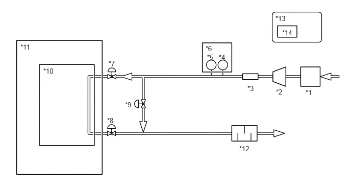
| *1 | Mass Air Flow Meter Sub-assembly | *2 | FC Air Compressor |
| *3 | Intercooler | *4 | FC Stack Inlet Air Temperature Sensor |
| *5 | FC Stack Inlet air Temperature Sensor | *6 | Vacuum Sensor Assembly |
| *7 | FC Air Pressure Regulator Assembly (Air Sealing Valve) | *8 | FC Air Pressure Regulator Assembly (Air Pressure Regulating Valve) |
| *9 | FC Air By-pass Valve Assembly (Air Shunt Valve) | *10 | FC Stack |
| *11 | FC Stack Assembly | *12 | FC Exhaust Tailpipe Assembly |
| *13 | EV Control ECU | *14 | Atmosphere Pressure Sensor |
| DTC No. | Detection Item | DTC Detection Condition | Trouble Area | Warning Indicate | DTC Output from | Priority |
|---|---|---|---|---|---|---|
| P1E4862 | FC Stack Inlet Pressure Sensor/Barometric Pressure Sensor "B" Signal Compare Failure | Malfunction detection is performed when the following condition is met with the ignition switch ON.
Difference between the outputs of the atmosphere pressure sensor (built into the EV control ECU) and the FC stack inlet air pressure sensor (turbo pressure sensor) has exceeded a threshold. ·
Difference between the outputs of the atmosphere pressure sensor (built into the EV control ECU) and the FC stack inlet air pressure sensor (vacuum sensor assembly) has exceeded a threshold. ·
The EV control ECU (atmosphere pressure sensor) is outside the usage range ·
The FC stack inlet air pressure sensor (vacuum sensor assembly) is outside the usage range (1 trip detection logic) |
·
FC stack inlet air pressure sensor (vacuum sensor assembly) ·
EV control ECU (atmosphere pressure sensor) |
Master Warning: Comes on | EV | B |
| Vehicle Condition | FC shutdown
(ignition switch ON) |
FC startup process | FC intermittent operation | FC is generating power
(vehicle is in stationary) |
FC is generating power
(vehicle is traveling) |
FC shutdown process |
|---|---|---|---|---|---|---|
| Data List
"FC Work Mode" |
Stop | Startup | Working | Finishing | ||
| Data List
"FC Intermittent Operation" |
OFF | ON | OFF | OFF | ||
| DTC Detection | ○ | - | - | - | - | - |
- HINT:
-
The vehicle behavior when the FC stack inlet air pressure sensor (vacuum sensor assembly) is malfunctioning is different from that when the EV control ECU (atmosphere pressure sensor) is malfunctioning.
-
Click hereEngine / Hybrid System>FC CONTROL>FC CONTROL SYSTEM>VEHICLE BEHAVIOR CHART
| DTC No. | Data List |
|---|---|
| P1E4862 | ·
FC Inlet Air Pressure (Filtered Value) ·
Atmospheric Pressure |
- HINT:
-
After the FC system is activated, the value of "FC Inlet Air Pressure (Filtered Value)" varies depending on the driving conditions.
CAUTION / NOTICE / HINT
- NOTICE:
- ·
This vehicle performs FC system shutdown process after turning the ignition switch off from ON (READY). Therefore, after the ignition switch is turned off from ON (READY), do not perform any work on the electrical system for at least 10 minutes including removing connectors or disconnecting the negative (-) auxiliary battery terminal.
·When the EV control ECU determines that the temperature of FC system components is below 0°C (32°F) when the vehicle is parked with the ignition switch off, it operates the FC air compressor, hydrogen pump and FC cooling water pump for a maximum of 180 seconds to drain the FC stack assembly. When performing inspection or repairs with the ignition switch off (not ON or ON (READY)), disconnect the cable from the negative (-) auxiliary battery terminal before performing work. (If the auxiliary battery voltage is needed to conduct inspection, perform the inspection in an environment with an ambient temperature of 10°C (50°F) or higher.)
- HINT:
-
After the repair, clear the DTCs and perform the following procedure to check that DTCs are not output.
- 1.
Turn the ignition switch to ON and wait for 5 seconds.
PROCEDURE
- NOTICE:
-
The freeze frame data is cleared when DTCs are cleared. Be sure to make a note of necessary data in advance.
- HINT:
-
If P222F62 is output simultaneously, the atmospheric pressure sensor (EV control ECU) may be malfunctioning.
Pre-procedure1
None
Procedure1
According to the display on the GTS, check for DTCs in the Health Check.
- Result:
Result Proceed to Only P1E4862 is output A P1E4862 is output and DTCs other than the DTCs in the table below are output B P1E4862 is output and any DTCs in the table below are output C
Malfunction Content Relevant DTC System malfunction P1DC500 (EV) FC Air Pressure Too High
- HINT:
-
DTC P1E4862 may be store due to problems that cause the DTCs shown above to output. If such happens, troubleshoot the suspected area(s) corresponding to the output DTC(s) in order of the listed DTCs shown in the table above.
Post-procedure1
Turn the ignition switch off.
A
B
C
Pre-procedure1
None
Procedure1
Read the freeze frame data of DTC P1E4862.
- Powertrain > EV > DTC(P1E4862) > Freeze Frame Data
-
Tester Display Atmospheric Pressure FC Inlet Air Pressure (Filtered Value) - 50040 397 888,891 P1E4862
- Result:
Result Proceed to The value of FC Inlet Air Pressure (Filtered Value) is 55 kPa(abs) or less A The value of Atmospheric Pressure is 110 kPa(abs) or more, or 55 kPa(abs) or less B None of the above conditions are met C
Post-procedure1
Turn the ignition switch off.
A
B
C
Pre-procedure1
None
Procedure1
Clear the DTCs.
- Powertrain > EV > Clear DTCs
- 50002 397
- Result:
Proceed to NEXT
Post-procedure1
Turn the ignition switch off and wait for 10 minutes or more.
NEXT
Pre-procedure1
None
Procedure1
Read the value displayed on the GTS.
- Powertrain > EV > Data List
-
Tester Display Atmospheric Pressure FC Inlet Air Pressure (Filtered Value) - 50003 397 888,891
Using the table, read the normal atmospheric pressure value for the applicable altitude.
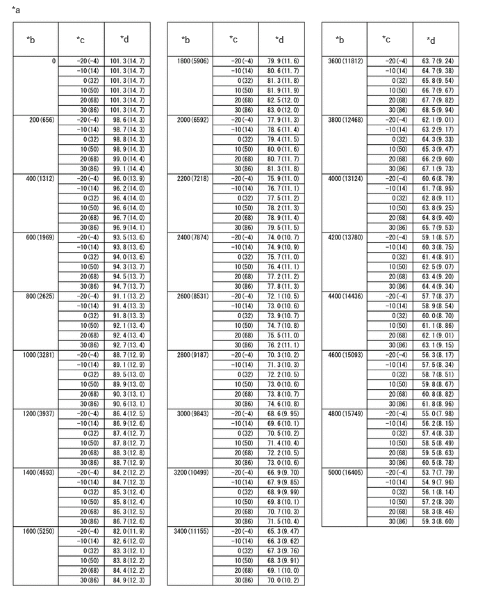
| *a | Altitude, Temperature and Atmospheric Pressure Correlation Table | *b | Altitude (m (ft.)) |
| *c | Temperature (°C (°F)) | *d | Atmospheric Pressure (kPa (psi)) |
- HINT:
- ·
Standard atmospheric pressure is approximately 101 kPa (15 psi).
·For every 100 m (328 ft.) increase in altitude, atmospheric pressure drops by approximately 1 kPa (0.1 psi). This varies by weather.
Compare the "FC Inlet Air Pressure (Filtered Value)" and "Atmospheric Pressure" values in the Data List with the normal atmospheric value from the table.
- NOTICE:
-
If the Data List values do not reproduce the symptom, check the values in the freeze frame data. Locate a malfunctioning area from the correlation between the 2 pressure sensor values.
- Result:
Result Proceed to Difference between "FC Inlet Air Pressure (Filtered Value)" in Data List and normal atmospheric pressure value is 10 kPa or more. A Difference between "Atmospheric Pressure" in Data List and normal atmospheric pressure value is 10 kPa or more. B Other than above. C
Post-procedure1
Turn the ignition switch off.
A
B
C
Click hereGeneral>INTRODUCTION>HOW TO TROUBLESHOOT ECU CONTROLLED SYSTEMS>HOW TO PROCEED WITH TROUBLESHOOTING