FC CONTROL FC CONTROL SYSTEM U116087 Lost Communication with FCDC Control Module Missing Message
DESCRIPTION
The EV control ECU and FC boost control ECU send and receive signals via CAN communication.
| DTC No. | Detection Item | DTC Detection Condition | Trouble Area | Warning Indicate | DTC Output from | Priority |
|---|---|---|---|---|---|---|
| U116087 | Lost Communication with FCDC Control Module Missing Message | A CAN communication error between the EV control ECU and FC boost control ECU (CAN communication system malfunction) occurs.
(1 trip detection logic) |
·
CAN communication system ·
FC boost control ECU ·
EV control ECU |
Master Warning: Comes on | EV | B |
CAUTION / NOTICE / HINT
- CAUTION:
- ·
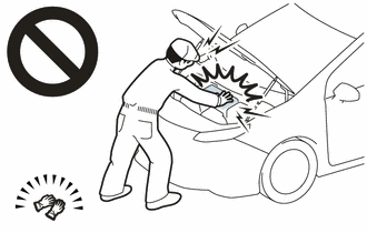
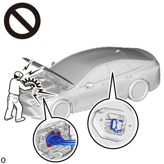
Before the following operations are conducted, take precautions to prevent electric shock by turning the ignition switch off, wearing insulated gloves, and removing the EV supply battery assembly service plug grip and FC converter power outlet cable (inverter with converter assembly) on FC converter side.
Make sure to remove the EV supply battery assembly service plug grip first.
-Inspecting the high-voltage system
-Disconnecting the low voltage connector of the inverter with converter assembly
-Disconnecting the low voltage connector of the EV supply battery assembly
-Disconnecting the low voltage connector of the FC converter assembly
·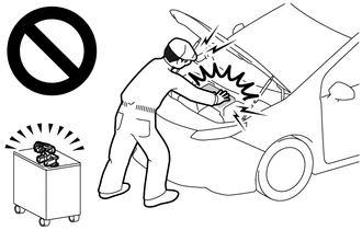
After removing the service plug grip from the EV supply battery assembly, put it in your pocket to prevent other technicians from accidentally reconnecting it while you are working on the high-voltage system. After removing the FC converter power outlet cable (inverter with converter assembly) on FC converter side and use the "HIGH-VOLTAGE, DO NOT TOUCH" sign to notify other technicians that you are working on the high-voltage system.
·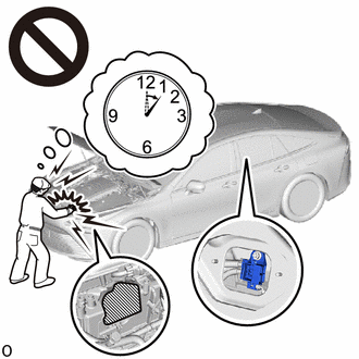
After removal of the EV supply battery assembly service plug grip and FC converter power outlet cable (inverter with converter assembly) on FC converter side, wait for at least 10 minutes before touching the high-voltage connectors and terminals. After waiting for 10 minutes, check the voltage at the terminals in the inspection point in the inverter with converter assembly. The voltage should be 0 V before beginning work.
Click hereEngine / Hybrid System>FC CONTROL>FC CONTROL SYSTEM>PRECAUTION
- HINT:
-
At least 10 minutes are necessary to discharge the high-voltage capacitors inside the inverter with converter assembly and FC stack assembly.
·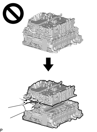
Since high voltage accumulates within the FC stack assembly with FC converter, never perform the work of separating the FC stack assembly with FC converter into the FC converter assembly and FC stack assembly without first performing electrical charge discharge (forced electrical charge discharge or electrical charge self-discharge), because doing so is dangerous.
Click hereEngine / Hybrid System>FC CONTROL>FC STACK>REMOVAL
·Removing and installing the FC stack assembly without first discharging the electrical charge may result in an electric shock due to the high voltage circuit.
- NOTICE:
- ·
When reinstalling the service plug grip to the EV supply battery assembly, after lowering the EV supply battery assembly service plug grip 90°, securely slide it until a "click" sound is heard.
Click hereEngine / Hybrid System>FC CONTROL>FC CONTROL SYSTEM>PRECAUTION
·When measuring the resistance of the CAN bus, turn the ignition switch off, wait for at least 1 minute without operating the key, operating any switches, or opening or closing any doors, then disconnect the auxiliary battery cable and wait again for at least 1 minute before measuring the resistance.
·Inspect the fuses of circuits related to this system before performing the following procedure.
·This vehicle performs FC system shutdown process after turning the ignition switch off from ON (READY). Therefore, after the ignition switch is turned off from ON (READY), do not perform any work on the electrical system for at least 10 minutes including removing connectors or disconnecting the negative (-) auxiliary battery terminal.
·When the EV control ECU determines that the temperature of FC system components is below 0°C (32°F) when the vehicle is parked with the ignition switch off, it operates the FC air compressor, hydrogen pump and FC cooling water pump for a maximum of 180 seconds to drain the FC stack assembly. When performing inspection or repairs with the ignition switch off (not ON or ON (READY)), disconnect the cable from the negative (-) auxiliary battery terminal before performing work. (If the auxiliary battery voltage is needed to conduct inspection, perform the inspection in an environment with an ambient temperature of 10°C (50°F) or higher.)
- HINT:
-
After the repair, clear the DTCs and perform the following procedure to check that DTCs are not output.
- 1.
Turn the ignition switch to ON and wait for 2 minutes or more.
PROCEDURE
- HINT:
-
Click herePower Source / Network>NETWORKING>CAN COMMUNICATION SYSTEM>HOW TO PROCEED WITH TROUBLESHOOTING
- Result:
Proceed to NEXT
NEXT