FC CONTROL FC CONTROL SYSTEM P1F089F FC Shutdown Signal Stuck Off
DESCRIPTION
Power supply to the hydrogen injector and exhaust drainage valve is shut down by a shutdown signal sent from the EV control ECU to the FC control ECU.
FCSD (FC shutdown signal) is sent from the EV control ECU to the FC control ECU immediately after startup with the ignition switch ON (READY) and when the ignition switch is turned off (READY), and the FC gate shutdown function check is performed. This DTC is detected if a malfunction is found in the FC gate shutdown function.
| DTC No. | Detection Item | DTC Detection Condition | Trouble Area | Warning Indicate | DTC Output from | Priority |
|---|---|---|---|---|---|---|
| P1F089F | FC Shutdown Signal Stuck Off | Malfunction detected if any of the following conditions is met while checking the FC gate shutdown function:
·
When checking the FC control ECU shutdown function (when the ignition switch is switched from ON (READY) to off), when "Low-Range Hydrogen Pressure (Filtered Value)" decreases (the exhaust drainage valve is operated) or when "Low-Range Hydrogen Pressure (Filtered Value)" increases (the hydrogen injector is operated). ·
The FCSD output command*1 and FCSD monitor value*2 are compared and found to be inconsistent when the ignition switch is ON (READY) or the ignition switch is off (READY) (1 trip detection logic)
|
·
EV control ECU ·
FC control ECU ·
Wire harness or connector |
Master Warning: Comes on | EV | A |
| DTC No. | Data List |
|---|---|
| P1F089F | ·
Ready Lighting Request (Normal Start) ·
FC System Status ·
Low-Range Hydrogen Pressure (Filtered Value) |
WIRING DIAGRAM
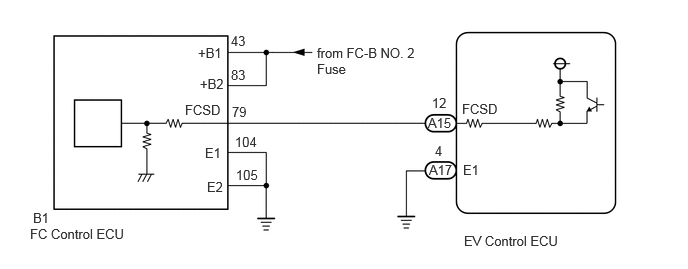
CAUTION / NOTICE / HINT
- NOTICE:
- ·
This vehicle performs FC system shutdown process after turning the ignition switch off from ON (READY). Therefore, after the ignition switch is turned off from ON (READY), do not perform any work on the electrical system for at least 10 minutes including removing connectors or disconnecting the negative (-) auxiliary battery terminal.
·When the EV control ECU determines that the temperature of FC system components is below 0°C (32°F) when the vehicle is parked with the ignition switch off, it operates the FC air compressor, hydrogen pump and FC cooling water pump for a maximum of 180 seconds to drain the FC stack assembly. When performing inspection or repairs with the ignition switch off (not ON or ON (READY)), disconnect the cable from the negative (-) auxiliary battery terminal before performing work. (If the auxiliary battery voltage is needed to conduct inspection, perform the inspection in an environment with an ambient temperature of 10°C (50°F) or higher.)
- HINT:
-
After the repair, clear the DTCs and perform the following procedure to check that DTCs are not output.
- 1.
Turn the ignition switch to ON and wait for 5 seconds or more.
2.Turn the ignition switch to ON (READY) and wait for 120 seconds or more.
3.Turn the ignition switch off and wait for 10 minutes or more.
4.Turn the ignition switch to ON (READY) and wait for 120 seconds or more.
5.Turn the ignition switch off and wait for 10 minutes or more.
PROCEDURE
Check the connector connections and contact pressure of the relevant terminals for the EV control ECU connectors.
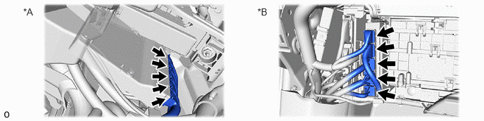
| *A | for LHD | *B | for RHD |
- OK:
The connectors are connected securely and there are no contact pressure problems.
- Result:
Result Proceed to OK A NG (The connector is not connected securely) B NG (The terminals are not making secure contact or are deformed, or water or foreign matter exists in the connector) C
A
B
C
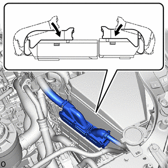
Check the connection condition of the FC control ECU connector and the contact pressure of each terminal. Check the terminals for deformation, and check the connector for water ingress and foreign matter.
- NOTICE:
-
Before disconnecting the connector, confirm that it is properly connected by checking that the locking claws are engaged and that the connector does not pull out.
- OK:
- The connector is connected securely.
- The terminals are not deformed and are connected securely.
- No water or foreign matter in the connector.
- HINT:
-
When connecting the connector, connect it with the lock levers raised. Rotate each lock lever downward and make sure that the connector is securely connected. When a lock lever is fully lowered, a click will be heard as its claw engages. After the click is heard, pull up on the connector to confirm that it is securely connected.
- Result:
Result Proceed to OK A NG (The connector is not connected securely) B NG (The terminals are not making secure contact or are deformed, or water or foreign matter exists in the connector) C
A
B
C
Pre-procedure1
Disconnect the FC control ECU connector.
Disconnect the EV control ECU connector.
Procedure1
Measure the resistance according to the value(s) in the table below.
- Standard Resistance:
Tester Connection Switch Condition Specified Condition Click Location & Routing(A15,B1)Location & Routingewd_type=routing;type=c,c;code=A15,B1
Click Connector(A15)Instrument Panel>Front Compartment Main Wire>EV Control ECUewd_type=component;type=c;code=A15;pinno=12
Click Connector(B1)Engine Compartment>No. 2 Stack Wire>FC Control ECUewd_type=component;type=c;code=B1;pinno=79
A15-12 (FCSD) - B1-79 (FCSD) Always Below 1 Ω A15-12 (FCSD) or B1-79 (FCSD) - Body ground and other terminals Always 10 kΩ or higher
- Result:
Proceed to OK NG
Post-procedure1
Connect the EV control ECU connector.
Connect the FC control ECU connector.
OK
NG
Pre-procedure1
Disconnect the EV control ECU connector.
Procedure1
Measure the resistance according to the value(s) in the table below.
- Standard Resistance:
Tester Connection Switch Condition Specified Condition Click Location & Routing(A15)Location & Routingewd_type=routing;type=c;code=A15
Click Connector(A15)Instrument Panel>Front Compartment Main Wire>EV Control ECUewd_type=component;type=c;code=A15;pinno=12
A15-12 (FCSD) - Body ground Ignition switch off 2.65 to 3.55 kΩ
- HINT:
-
A short circuit is confirmed from the connector on the EV control ECU to body ground on the FCSD terminal on the FC control ECU.
- Result:
Proceed to OK NG
Post-procedure1
Connect the EV control ECU connector.
OK
NG