FC CONTROL FCDC CONVERTER CONTROL ECU BOARD INSTALLATION
CAUTION / NOTICE / HINT
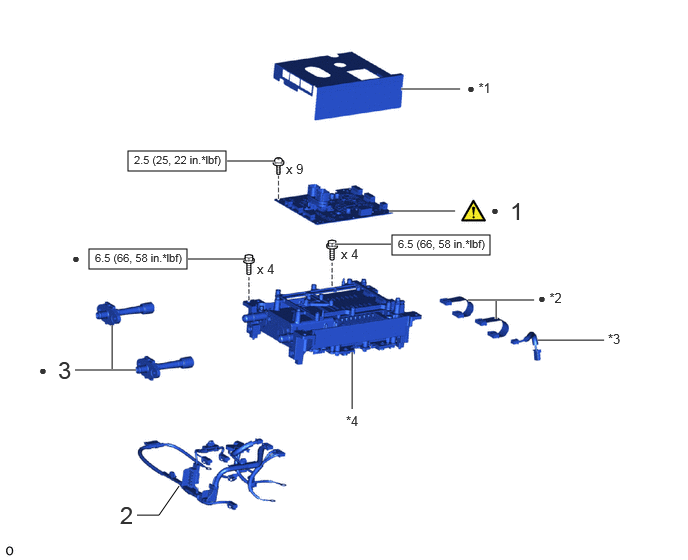
| Procedure | Part Name Code | 
|

|

|
|
|---|---|---|---|---|---|
| 1 | FCDC CONVERTER CONTROL ECU BOARD SUB-ASSEMBLY | F160A | ( ) |
- | - |
| 2 | NO. 1 FC CONVERTER WIRE | G9A1C | - | - | - |
| 3 | FC CONVERTER COOLING PIPE | G9A43 | - | - | - |
| *1 | FC CONVERTER SHEET | *2 | ECU WIRE SUB-ASSEMBLY |
| *3 | NO. 3 FC CONVERTER WIRE | *4 | FC CONVERTER POWER MODULE TRANSISTOR (IPM) |

|
N*m (kgf*cm, ft.*lbf): Specified torque | ● | Non-reusable part |
PROCEDURE

 F160A
1.INSTALL FCDC CONVERTER CONTROL ECU BOARD SUB-ASSEMBLY
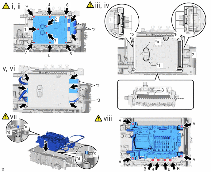
| *1 | Low Voltage Connector | *2 | ECU Wire Sub-assembly |
| *3 | NO. 3 FC Converter Wire | - | - |
| *a | FC converter sheet hole | *b | Connector Hole |
| *c | Knock Pin | *d | Pin Hole |
Using the magnetic screwdriver of the FC converter power module transistor kit, install a new FCDC converter control ECU board sub-assembly with the 9 screws in the order shown in the illustration.
- Torque:
- 2.5 N*m (25 kgf*cm, 22 in.*lbf)
- NOTICE:
-
Do not drop screws on the FCDC converter control ECU board sub-assembly.
Connect the 2 connectors and install the 2 new ECU wire sub-assemblies.
Insert and position the low voltage connector in the hole on the FC converter sheet as shown in the illustration.
Remove the peeling paper on a new FC converter sheet while making sure not to touch the adhesional surface.
Attach the new FC converter sheet to the FC converter power module transistor (IPM) as shown in the illustration.
- NOTICE:
- ·
Do not touch the adhesive part of the double-sided tape.
·Check that there is no foreign matter or other substances that could affect adhesiveness on the double-sided tape application surface.
·Attach so that the connector holes are not blocked.
·Do not to apply excessive force to the FCDC converter control ECU board sub-assembly when attaching it.
- HINT:
-
It is recommended to attach in the order shown in the illustration.
Connect the connector and install the No. 3 FC converter wire.
Connect the 5 connectors.
- NOTICE:
-
Do not apply excessive force to the FCDC converter control ECU board sub-assembly connector.
Align the knock pin on the FC converter power module transistor (IPM) with the pinhole on the case, and set the FC converter power module transistor (IPM).
Install the FC converter power module transistor (IPM) with the 4 new bolts (A) and 4 bolts (B).
- Torque:
- for bolt A : 6.0 N*m (61 kgf*cm, 53 in.*lbf)
- for bolt B : 6.5 N*m (66 kgf*cm, 58 in.*lbf)
- NOTICE:
- ·
Clean the hole for bolt A and the bolt A installation area.
·Tighten the 8 bolts in the order of (A) and (B).
G9A1C
2.CONNECT NO. 1 FC CONVERTER WIRE
G9A43
3.INSTALL FC CONVERTER COOLING PIPE