| NG |  |
| ADJUST VALVE TIMING |
DTC P0011 Camshaft Position "A" - Timing Over-Advanced or System Performance (Bank 1) |
DTC P0012 Camshaft Position "A" - Timing Over-Retarded (Bank 1) |
| DTC No. | DTC Detection Condition | Trouble Area |
| P0011 | Valve timing is not adjusted in valve timing advance range (1 trip detection logic) |
|
| P0012 | Valve timing is not adjusted in valve timing retard range (2 trip detection logic) |
|
| Related DTCs | P0011: VVT system advance (bank 1) P0012: VVT system retard (bank 1) |
| Required sensors/components | Main sensors: Camshaft timing gear assembly Oil control valve Related sensors: Camshaft position sensor Engine coolant temperature sensor Crankshaft position sensor |
| Frequency of operation | Once per driving cycle |
| Duration | Within 10 seconds |
| MIL operation | P0011: Immediately P0012: 2 driving cycles |
| Sequence of operation | None |
| The monitor will run whenever the following DTCs are not present | P0100 - P0103 (MAF meter) P0115 - P0118 (ECT sensor) P0125 (Insufficient ECT for closed loop) P0335 (CKP sensor) P0340, P0341 (CMP sensor) P0351-P0354 (Igniter) |
| Battery voltage | 11 V or more |
| Engine speed | 900 to 5,000 rpm |
| Engine coolant temperature | 75 to 100°C (167 to 212°F) |
| Both of the following conditions are met: | 1 and 2 |
| 1. Deviation of valve timing | More than 5°CA |
| 2. Valve timing | No change at advanced valve timing |
| Both of the following conditions are met: | 1 and 2 |
| 1. Deviation of valve timing | More than 5°CA |
| 2. Valve timing | No change at retarded valve timing |
| 1.CHECK VALVE TIMING (CHECK FOR LOOSE AND A JUMPED TOOTH OF TIMING CHAIN) |
|
| ||||
| OK | |
 |
| 2.PERFORM ACTIVE TEST BY TECHSTREAM (OPERATE OCV) |
Connect Techstream to the DLC3.
Turn the power switch ON (IG).
Turn Techstream ON.
Put the engine in inspection mode (Click here).
Start the engine and warm it up.
Enter the following menus: Powertrain / Engine and ECT / Active Test / Control the VVT System (Bank 1).
Using Techstream, operate the OCV and check the engine speed.
| Tester Operation | Specified Condition |
| OCV is OFF | Normal engine speed |
| OCV is ON | Rough idle or engine stall |
|
| ||||
| OK | |
|
| 3.CHECK IF DTC OUTPUT RECURS |
Clear the DTCs (Click here).
Start the HV main system and warm the engine up.
Drive the vehicle with the shift position in B at vehicle speed of more than 44 mph (70 km/h) approximately for 10 minutes or more.
Read output DTCs using Techstream.
|
| ||||
| NG | |
|
| 4.INSPECT OIL CONTROL VALVE FILTER |
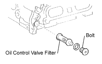 |
Remove the air cleaner inlet, bolt and oil control valve filter.
Check for cloggings in the oil control valve filter.
Reinstall the filter, bolt and air cleaner inlet.
|
| ||||
| OK | |
|
| 5.INSPECT CAMSHAFT TIMING OIL CONTROL VALVE ASSEMBLY (OCV) |
|
| ||||
| OK | |
|
| 6.REPLACE CAMSHAFT TIMING GEAR ASSEMBLY |
| NEXT | |
|
| 7.CHECK IF DTC OUTPUT RECURS |
Clear the DTCs (Click here).
Start the HV system, and warm the engine up.
Drive the vehicle with the shift position in B at vehicle speed of more than 70 km/h (44 mph) approximately for 10 minutes or more.
Read output DTCs using Techstream.
|
| ||||
| OK | ||
 | ||
| ||
