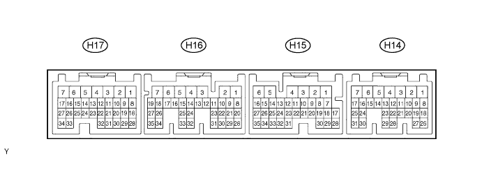
HYBRID CONTROL SYSTEM > TERMINALS OF ECU |
| Symbols (Terminal No.) | Wiring Color | Terminal Description | Condition | STD Voltage (V) |
| ST2 (H14-5) - GND1 (H14-1) | Y - W-B | Starter signal | Power switch ON (READY) | 9 to 14 |
| IGSW (H14-7) - GND1 (H14-1) | O - W-B | IG signal | Power switch ON (IG) | 9 to 14 |
| IGSW (H14-7) - GND1 (H14-1) | O - W-B | IG signal | Power switch OFF to ON (READY) | Pulse generation (see waveform 9) |
| IGSW (H14-7) - GND1 (H14-1) | O - W-B | IG signal | Power switch ON (IG) and A/C operating | Pulse generation (see waveform 19) |
| BATT (H15-6) - GND1 (H14-1) | Y - W-B | Auxiliary battery (for measuring the battery voltage and for the HV control ECU memory) | Always | 9 to 14 |
| +B1 (H16-7) - GND1 (H14-1) | L - W-B | Power source of HV control ECU | Power switch ON (IG) | 9 to 14 |
| +B2 (H16-6) - GND1 (H14-1) | L - W-B | Power source of HV control ECU | Power switch ON (IG) | 9 to 14 |
| MREL (H16-4) - GND1 (H14-1) | O - W-B | Main relay | Power switch ON (IG) | 9 to 14 |
| CANH (H14-8) - GND1 (H14-1) | B - W-B | HIGH-level CAN bus line | Power switch ON (IG) | Pulse generation (see waveform 1) |
| CANL (H14-9) - GND1 (H14-1) | W - W-B | LOW-level CAN bus line | Power switch ON (IG) | Pulse generation (see waveform 2) |
| NEO (H16-12) - GND1 (H14-1) | LG - W-B | Engine speed signal | Engine running | Pulse generation (see waveform 3) |
| GO (H16-13) - GND1 (H14-1) | Y - W-B | G signal | Engine running | Pulse generation (see waveform 4) |
| SPDI (H14-19) - GND1 (H14-1) | V - W-B | Vehicle speed signal | Driving at approximately 12 mph (20 km/h) | Pulse generation (see waveform 5) |
| VPA1 (H16-26) - EP1 (H16-27) | L - B | Accelerator pedal position sensor (for the HV system) | Power switch ON (IG), accelerator pedal released | 0.5 to 1.1 |
| VPA1 (H16-26) - EP1 (H16-27) | L - B | Accelerator pedal position sensor (for the HV system) | Power switch ON (IG), engine stopped in P position, accelerator pedal fully depressed | 2.6 to 4.5 |
| VPA2 (H16-34) - EP2 (H16-35) | W - R | Accelerator pedal position sensor (for the sensor malfunction detection) | Power switch ON (IG), accelerator pedal fully depressed | 1.2 to 2.0 |
| VPA2 (H16-34) - EP2 (H16-35) | W - R | Accelerator pedal position sensor (for the sensor malfunction detection) | Power switch ON (IG), engine stopped in P position, accelerator pedal released | 3.4 to 5.3 |
| VCP1 (H16-25) - EP1 (H16-27) | Y - B | Power source of accelerator pedal position sensor (for VPA1) | Power switch ON (IG) | 4.5 to 5.5 |
| VCP2 (H16-33) - EP2 (H16-35) | G - R | Power source of accelerator pedal position sensor (for VPA2) | Power switch ON (IG) | 4.5 to 5.5 |
| VSX1 (H14-25) - E2X1 (H14-15) | B - R | Shift position sensor (main) | Power switch ON (IG), selector lever home position | 2.0 to 3.0 |
| VSX1 (H14-25) - E2X1 (H14-15) | B - R | Shift position sensor (main) | Power switch ON (IG), selector lever moved to R position | 4.0 to 4.8 |
| VSX1 (H14-25) - E2X1 (H14-15) | B - R | Shift position sensor (main) | Power switch ON (IG), selector lever moved to B or D position | 0.2 to 1.0 |
| VSX2 (H14-24) - E2X2 (H14-14) | L - Y | Shift position sensor (sub) | Power switch ON (IG), selector lever home position | 2.0 to 3.0 |
| VSX2 (H14-24) - E2X2 (H14-14) | L - Y | Shift position sensor (sub) | Power switch ON (IG), selector lever moved to R position | 4.0 to 4.8 |
| VSX2 (H14-24) - E2X2 (H14-14) | L - Y | Shift position sensor (sub) | Power switch ON (IG), selector lever moved to B or D position | 0.2 to 1.0 |
| VCX1 (H14-17) - E2X1 (H14-15) | W - R | Power source of shift position sensor (for VSX1) | Power switch ON (IG) | 4.5 to 5.5 |
| VCX2 (H14-16) - E2X2 (H14-14) | G - Y | Power source of shift position sensor (for VSX2) | Power switch ON (IG) | 4.5 to 5.5 |
| VSX3 (H14-23) - GND1 (H14-1) | BR - W-B | Select position sensor (main) | Power switch ON (IG), selector lever home position | 0.5 to 2.0 |
| VSX3 (H14-23) - GND1 (H14-1) | BR - W-B | Select position sensor (main) | Power switch ON (IG), selector lever moved to R, N or D position | 3.0 to 4.85 |
| VSX4 (H14-30) - GND1 (H14-1) | SB - W-B | Select position sensor (sub) | Power switch ON (IG), selector lever home position | 0.5 to 2.0 |
| VSX4 (H14-30) - GND1 (H14-1) | SB- W-B | Select position sensor (sub) | Power switch ON (IG), selector lever moved to R, N or D position | 3.0 to 4.85 |
| VCX3 (H14-21) - GND1 (H14-1) | W - W-B | Power source of select position sensor (for VSX3) | Power switch ON (IG) | 9 to 14 |
| VCX4 (H14-31) - GND1 (H14-1) | P - W-B | Power source of select position sensor (for VSX4) | Power switch ON (IG) | 9 to 14 |
| NODD (H16-24) - GND1 (H14-1) | V - W-B | DC / DC movement monitor or stop request signal | When converter is in normal operation | 5 to 7 |
| NODD (H16-24) - GND1 (H14-1) | V - W-B | DC / DC movement monitor or stop request signal | When converter is improper | 2 to 4 |
| NODD (H16-24) - GND1 (H14-1) | V - W-B | DC / DC movement monitor or stop request signal | When converter is required to stop | 0.1 to 0.5 |
| VLO (H16-31) - GND1 (H14-1) | L - W-B | Two-stage selector signal | Converter switching to 14 V output | 13 to 14 |
| VLO (H16-31) - GND1 (H14-1) | L - W-B | Two-stage selector signal | Converter switching to 13.5 V output | Below 0.5 |
| TC (H14-6) - GND1 (H14-1) | P - W-B | Terminal TC of DLC3 | Power switch ON (IG) | 9 to 14 |
| STP (H15-3) - GND1 (H14-1) | L - W-B | Stop light switch | Brake pedal depressed | 9 to 14 |
| STP (H15-3) - GND1 (H14-1) | L - W-B | Stop light switch | Brake pedal released | 2 to 3 |
| ABFS (H14-20) - GND1 (H14-1) | L - W-B | Airbag deployment signal | Power switch ON (READY) (2 seconds after ON [ACC] ) | Pulse generation (see waveform 6, 7, 8) |
| AS1 (H16-15) - AS1G (H16-16) | Y - W | No. 1 circuit breaker sensor | Satellite signal system normal | 2.5 to 2.9 |
| ILK (H15-1) - GND1 (H14-1) | V - W-B | Interlock switch | Power switch ON (IG), inverter cover and service plug grip installed normally | Below 1 |
| ILK (H15-1) - GND1 (H14-1) | V - W-B | Interlock switch | Power switch ON (IG), inverter cover or service plug grip detached | 9 to 14 |
| CON1 (H16-1) - GND1 (H14-1) | R - W-B | No. 1 system main relay | Power switch OFF to ON (READY) | Pulse generation (see waveform 9) |
| CON2 (H16-2) - GND1 (H14-1) | G - W-B | No. 2 system main relay | Power switch OFF to ON (READY) | Pulse generation (see waveform 9) |
| CON3 (H16-3) - GND1 (H14-1) | Y - W-B | No. 3 system main relay | Power switch OFF to ON (READY) | Pulse generation (see waveform 9) |
| VH (H15-26) - GINV (H15-23) | Y - Y | Inverter condenser voltage monitor | Power switch ON (READY) | 1.6 to 3.8 |
| GUU (H15-15) - GINV (H15-23) | B - Y | Generator switch U signal | Power switch ON (IG) | Pulse generation (see waveform 10) |
| GVU (H15-14) - GINV (H15-23) | G - Y | Generator switch V signal | Power switch ON (IG) | Pulse generation (see waveform 10) |
| GWU (H15-13) - GINV (H15-23) | Y - Y | Generator switch W signal | Power switch ON (IG) | Pulse generation (see waveform 10) |
| GIVA (H15-34) - GINV (H15-23) | W - Y | Generator V phase current | Power switch ON (IG) | Approximately 0 |
| GIVB (H15-33) - GINV (H15-23) | B - Y | Generator V phase current | Power switch ON (IG) | Approximately 0 |
| GIWA (H15-32) - GINV (H15-23) | R - Y | Generator W phase current | Power switch ON (IG) | Approximately 0 |
| GIWB (H15-31) - GINV (H15-23) | G - Y | Generator W phase current | Power switch ON (IG) | Approximately 0 |
| GIVT (H15-27) - GINV (H15-23) | W - Y | Generator inverter temperature sensor | Power switch ON (IG) | 2 to 4.5 |
| GSDN (H15-16) - GINV (H15-23) | R - Y | Generator shutdown signal | Power switch ON (READY), N position | 0.2 to 0.7 |
| GSDN (H15-16) - GINV (H15-23) | R - Y | Generator shutdown signal | Power switch ON (READY), P position | 5.1 to 13.6 |
| GFIV (H15-35) - GINV (H15-23) | GR - Y | Generator inverter fail signal | Power switch ON (IG), inverter normal | 5.4 to 7.4 |
| GFIV (H15-35) - GINV (H15-23) | GR - Y | Generator inverter fail signal | Power switch ON (IG), inverter abnormal | 2 to 3 |
| GRF (H17-27) - GRFG (H17-26) | B - W | Generator resolver signal | Generator resolver stopped or rotating | Pulse generation (see waveform 11, 12) |
| GSN (H17-22) - GSNG (H17-21) | R - G | Generator resolver signal | Generator resolver stopped or rotating | Pulse generation (see waveform 11, 12) |
| GCS (H17-23) - GCSG (H17-24) | Y - BR | Generator resolver signal | Generator resolver stopped or rotating | Pulse generation (see waveform 11, 12) |
| OMT (H17-30) - OMTG (H17-29) | B - G | No. 2 motor temperature sensor | Refer to DATA LIST (Click here) | - |
| MUU (H15-9) - GINV (H15-23) | B - Y | Motor switch U signal | Power switch ON (IG) | Pulse generation (see waveform 13) |
| MVU (H15-10) - GINV (H15-23) | W - Y | Motor switch V signal | Power switch ON (IG) | Pulse generation (see waveform 13) |
| MWU (H15-11) - GINV (H15-23) | R - Y | Motor switch W signal | Power switch ON (IG) | Pulse generation (see waveform 13) |
| MIVA (H15-30) - GINV (H15-23) | G - Y | Motor V phase current | Power switch ON (IG) | Approximately 0 |
| MIVB (H15-21) - GINV (H15-23) | W - Y | Motor V phase current | Power switch ON (IG) | Approximately 0 |
| MIWA (H15-29) - GINV (H15-23) | R - Y | Motor W phase current | Power switch ON (IG) | Approximately 0 |
| MIWB (H15-20) - GINV (H15-23) | B - Y | Motor W phase current | Power switch ON (IG) | Approximately 0 |
| MIVT (H15-19) - GINV (H15-23) | L - Y | Motor inverter temperature sensor | Power switch ON (IG) | 2 to 4.5 |
| MSDN (H15-8) - GINV (H15-23) | G - Y | Motor shutdown signal | Power switch ON (READY), N position | 0.2 to 0.7 |
| MSDN (H15-8) - GINV (H15-23) | G - Y | Motor shutdown signal | Power switch ON (READY), P position | 5.1 to 13.6 |
| OVH (H15-22) - GINV (H15-23) | BR - Y | Motor inverter over voltage signal | Power switch ON (IG), inverter normal | 5.3 to 7.3 |
| OVH (H15-22) - GINV (H15-23) | BR - Y | Motor inverter over voltage signal | Power switch ON (IG), inverter abnormal | 1.9 to 2.9 |
| MFIV (H15-18) - GINV (H15-23) | G - Y | Motor inverter fail signal | Power switch ON (IG), inverter normal | 5.4 to 7.4 |
| MFIV (H15-18) - GINV (H15-23) | G - Y | Motor inverter fail signal | Power switch ON (IG), inverter abnormal | 2 to 3 |
| MRF (H17-34) - MRFG (H17-33) | L - P | Motor resolver signal | Motor resolver stopped or rotating | Pulse generation (see waveform 11, 12) |
| MSN (H17-20) - MSNG (H17-19) | G - R | Motor resolver signal | Motor resolver stopped or rotating | Pulse generation (see waveform 11, 12) |
| MCS (H17-32) - MCSG (H17-31) | Y - BR | Motor resolver signal | Motor resolver stopped or rotating | Pulse generation (see waveform 11, 12) |
| MMT (H17-18) - MMTG (H17-28) | B - R | No. 1 motor temperature sensor | Refer to DATA LIST (Click here) | - |
| VL (H16-30) - GCNV (H16-8) | Y - G | Boost converter input voltage | Power switch ON (READY) | 1.9 to 3.4 |
| OVL (H16-22) - GCNV (H16-8) | B - G | Boost converter over voltage signal | Power switch ON (IG), boost converter normal | 5.3 to 7.7 |
| OVL (H16-22) - GCNV (H16-8) | B - G | Boost converter over voltage signal | Power switch ON (IG), boost converter abnormal | 1.9 to 3.0 |
| FCV (H16-20) - GCNV (H16-8) | W - G | Boost converter fail signal | Power switch ON (IG), boost converter normal | 5.3 to 7.7 |
| FCV (H16-20) - GCNV (H16-8) | W - G | Boost converter fail signal | Power switch ON (IG), boost converter abnormal | 1.9 to 3.0 |
| CT (H16-21) - GCNV (H16-8) | R - G | Boost converter temperature sensor | Power switch ON (IG) | 2.0 to 4.5 |
| CPWM (H16-10) - GCNV (H16-8) | B - G | Boost converter PWM switch signal | Power switch ON (READY), parking brake ON, D position, brake pedal and accelerator pedal depressed | Pulse generation (see waveform 14) |
| CSDN (H16-9) - GCNV (H16-8) | W - G | Boost converter shutdown signal | Power switch ON (IG) | 5.6 or higher |
| CSDN (H16-9) - GCNV (H16-8) | W - G | Boost converter shutdown signal | Power switch ON (READY) | Below 0.7 |
| ST1- (H15-2) - GND1 (H14-1) | G - W-B | Stop light switch (opposite to STP) | Power switch ON (IG) and brake pedal depressed | Below 0.5 |
| ST1- (H15-2) - GND1 (H14-1) | G - W-B | Stop light switch (opposite to STP) | Power switch ON (IG) and brake pedal released | 9 to 14 |
| CCS (H14-13) - GND1 (H14-1) | V - W-B | Cruise control switch | Cruise control system - Terminal of ECU - CCS terminal (Click here) | - |
| IMI (H14-18) - GND1 (H14-1) | W - W-B | Immobiliser communication | Immobiliser communicating | Pulse generation (see waveform 15) |
| IMO (H14-26) - GND1 (H14-1) | R - W-B | Immobiliser communication | Immobiliser communicating | Pulse generation (see waveform 15) |
| P1 (H15-17) - GND1 (H14-1) | Y - W-B | P position switch | Power switch ON (IG), P position switch ON | 3 to 5 |
| P1 (H15-17) - GND1 (H14-1) | Y - W-B | P position switch | Power switch ON (IG), P position switch OFF | 7 to 12 |
| PCON (H17-9) - GND1 (H14-1) | LG - W-B | P position control signal | Power switch ON (IG) | Pulse generation (see waveform 16) |
| PPOS (H17-10) - GND1 (H14-1) | W - W-B | P position signal | Power switch ON (IG) | Pulse generation (see waveform 16) |
| RDY (H14-28) - GND1 (H14-1) | R - W-B | READY control signal | Power switch ON (IG) | Pulse generation (see waveform 17) |
| RDY (H14-28) - GND1 (H14-1) | R - W-B | READY control signal | Power switch ON (READY) | Pulse generation (see waveform 18) |
| CLK (H16-17) - GND1 (H14-1) | G - W-B | A/C communication | Power switch ON (IG), A/C operating | Pulse generation (see waveform 19) |
| ITE (H16-14) - GND1 (H14-1) | Y - W-B | A/C communication | Power switch ON (IG), A/C operating | Pulse generation (see waveform 19) |
| ETI (H15-24) - GND1 (H14-1) | R - W-B | A/C communication | Power switch ON (IG), A/C operating | Pulse generation (see waveform 19) |
| STB (H15-25) - GND1 (H14-1) | W - W-B | A/C communication | Power switch ON (IG), A/C operating | Pulse generation (see waveform 19) |
| WP (H16-5) - GND1 (H14-1) | O - W-B | Water pump relay control | Power switch ON (IG), A/C operating | Below 2 |
| GND1 (H14-1) - Body ground | W-B - Body ground | Ground | Always (resistance check) | Below 5 Ω |
| GND2 (H14-4) - Body ground | W-B - Body ground | Ground | Always (resistance check) | Below 5 Ω |
| Oscilloscope waveforms |
| Waveform 1 |
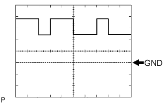 |
| Item | Contents |
| Terminal | CANH - GND1 |
| Equipment Setting | 1 V/Division, 2 μs/Division |
| Condition | Power switch ON (IG) |
| Waveform 2 |
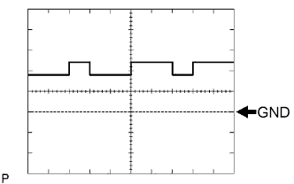 |
| Item | Contents |
| Terminal | CANL - GND1 |
| Equipment Setting | 1 V/Division, 2 μs/Division |
| Condition | Power switch ON (IG) |
| Waveform 3 |
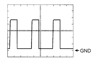 |
| Item | Contents |
| Terminal | NEO - GND1 |
| Equipment Setting | 1 V/Division, 2 ms/Division |
| Condition | Engine idling |
| Waveform 4 |
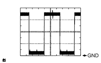 |
| Item | Contents |
| Terminal | GO - GND1 |
| Equipment Setting | 2 V/Division, 20 ms/Division |
| Condition | Engine idling |
| Waveform 5 |
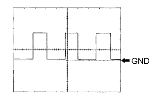 |
| Item | Contents |
| Terminal | SPDI - GND1 |
| Equipment Setting | 5 V/Division, 20 ms/Division |
| Condition | Driving at approximately 12 mph (20 km/h) |
| Waveform 6 |
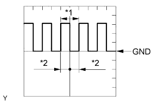 |
| Item | Contents |
| Terminal | ABFS - GND1 |
| Equipment Setting | 1 V/Division, 500 ms/Division |
| Condition | Power switch ON (READY) (2 seconds after ON [ACC]) Airbag system normal |
| Waveform 7 |
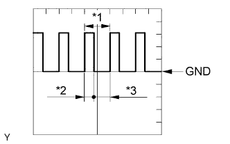 |
| Item | Contents |
| Terminal | ABFS - GND1 |
| Equipment Setting | 1 V/Division, 50 ms/Division |
| Condition | Power switch ON (READY) (2 seconds after ON [ACC]) Airbag system abnormal |
| Waveform 8 |
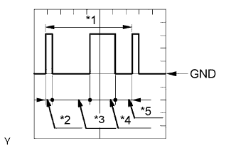 |
| Item | Contents |
| Terminal | ABFS - GND1 |
| Equipment Setting | 1 V/Division, 50 ms/Division |
| Condition | Power switch ON (READY) (2 seconds after ON [ACC]) Airbag system deployed (during collision) |
| Waveform 9 |
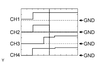 |
| Item | Contents |
| Terminal | CH1: IGSW - GND1 CH2: CON1 - GND1 CH3: CON2 - GND1 CH4: CON3 - GND1 |
| Equipment Setting | 10 V/Division, 100 ms/Division |
| Condition | Power switch OFF to ON (READY) |
| Waveform 10 |
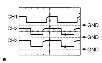 |
| Item | Contents |
| Terminal | CH1: GUU - GINV CH2: GVU - GINV CH3: GWU - GINV |
| Equipment Setting | 10 V/Division, 20 μs/Division |
| Condition | Power switch ON (IG) |
| Waveform 11 |
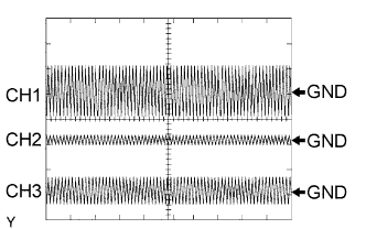 |
| Item | Contents |
| Terminal (Generator Resolver) | CH1: GRF - GRFG CH2: GSN - GSNG CH3: GCS - GCSG |
| Terminal (Motor Resolver) | CH1: MRF - MRFG CH2: MSN - MSNG CH3: MCS - MCSG |
| Equipment Setting | CH1: 10 V/Division, 1 ms/Division CH2, 3: 5 V/Division, 1 ms/Division |
| Condition | Generator or motor stopped |
| Waveform 12 |
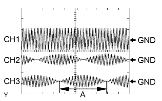 |
| Item | Contents |
| Terminal (Generator Resolver) | CH1: GRF - GRFG CH2: GSN - GSNG CH3: GCS - GCSG |
| Terminal (Motor Resolver) | CH1: MRF - MRFG CH2: MSN - MSNG CH3: MCS - MCSG |
| Equipment Setting | CH1: 10 V/Division, 1 ms/Division CH2, 3: 5 V/Division, 1 ms/Division |
| Condition | Generator or motor rotating |
| Waveform 13 |
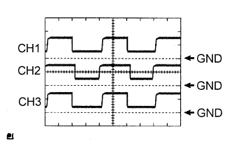 |
| Item | Contents |
| Terminal | CH1: MUU - GINV CH2: MVU - GINV CH3: MWU - GINV |
| Equipment Setting | 10 V/Division, 50 μs/Division |
| Condition | Power switch ON (IG) |
| Waveform 14 |
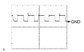 |
| Item | Contents |
| Terminal | CPWM - GCNV |
| Equipment Setting | 10 V/Division, 50 μs/Division |
| Condition | Power switch ON (READY), parking brake ON, D position, brake pedal and accelerator pedal depressed |
| Waveform 15 |
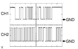 |
| Item | Contents |
| Terminal | CH1: IMO - GND1 CH2: IMI - GND1 |
| Equipment Setting | 5 V/Division, 200 ms/Division |
| Condition | Immobiliser communicating |
| Waveform 16 |
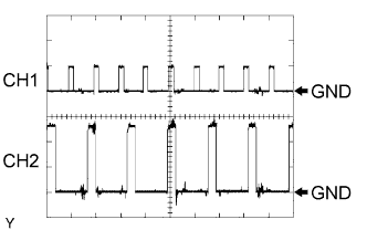 |
| Item | Contents |
| Terminal | CH1: PCON - GND1 CH2: PPOS - GND1 |
| Equipment Setting | 5 V/Division, 20 ms/Division |
| Condition | Power switch ON (IG) |
| Waveform 17 |
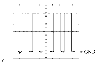 |
| Item | Contents |
| Terminal | RDY - GND1 |
| Equipment Setting | 2 V/Division, 20 ms/Division |
| Condition | Power switch ON (IG) |
| Waveform 18 |
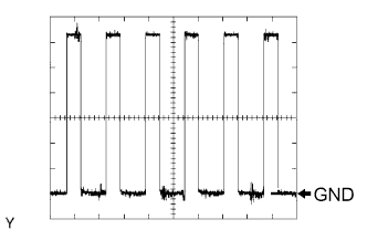 |
| Item | Contents |
| Terminal | RDY - GND1 |
| Equipment Setting | 2 V/Division, 20 ms/Division |
| Condition | Power switch ON (READY) |
| Waveform 19 |
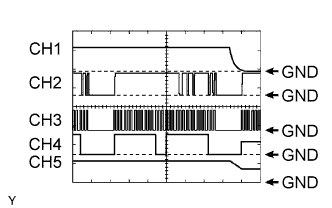 |
| Item | Contents |
| Terminal | CH1: IGSW - GND1 CH2: ITE - GND1 CH3: CLK - GND1 CH4: ETI - GND1 CH5: STB - GND1 |
| Equipment Setting | 10 V/Division, 50 ms/Division |
| Condition | Power switch ON (IG) and A/C operating |