 |
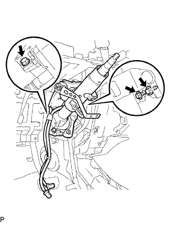
Install the steering column with the 3 bolts.
- Torque:
- 25 N*m{ 255 kgf*cm , 18 ft.*lbf }
STEERING COLUMN ASSEMBLY > INSTALLATION |
| 1. INSTALL STEERING COLUMN ASSEMBLY |
|
Install the steering column with the 3 bolts.
Connect the connectors and wire harness clamps to the steering column.
| 2. INSTALL STEERING SLIDING YOKE SUB-ASSEMBLY |
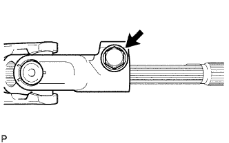 |
Temporarily install the steering sliding yoke sub-assembly to the steering intermediate shaft with the bolt.
| 3. INSTALL STEERING INTERMEDIATE SHAFT SUB-ASSEMBLY |
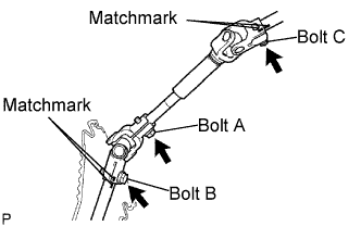 |
Align the matchmarks on the steering intermediate shaft assembly and steering column and install them with the bolt labeled C.
Align the matchmark on the steering intermediate shaft and steering intermediate shaft and install them with the bolt labeled B.
Tighten the bolt labeled A on the steering sliding yoke.
| 4. INSTALL COLUMN HOLE COVER SILENCER SHEET |
| 5. INSTALL FRONT FLOOR FOOTREST LH |
Attach the 2 clips to install the front floor footrest.
| 6. INSTALL POWER STEERING ECU ASSEMBLY |
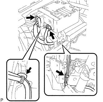 |
Connect the 2 steering column connectors to the power steering ECU.
Install the clamp holding the power steering motor and torque sensor wire harness on the bottom surface of the power steering computer.
Install the torque sensor wire harness clamp to the instrument panel reinforcement.
Make sure that the power steering motor and torque sensor wire harnesses do not interfere with other parts while tilting up and down the steering column.
| 7. INSTALL INSTRUMENT PANEL PASSENGER AIRBAG ASSEMBLY |
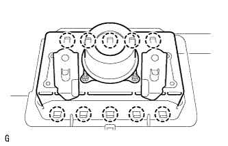 |
Attach the 10 claws to install the front passenger airbag.
| 8. DISCONNECT PASSENGER AIRBAG CONNECTOR |
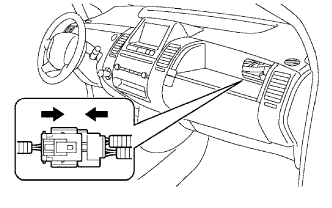 |
Connect the front passenger airbag connector.
| 9. INSTALL FRONT PILLAR GARNISH ASSEMBLY LH |
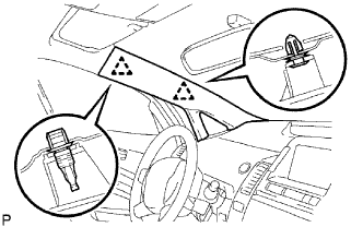 |
w/o Curtain Shield Airbag:
Attach the 2 clips to install the pillar garnish.
w/ Curtain Shield Airbag:
Remove the protective cover.
w/ Curtain Shield Airbag:
Install the pillar garnish.
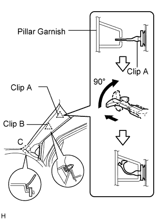 |
Set the claws of the pillar garnish to the area labeled C.
Insert the tip of clip A into the pillar garnish's hole.
Using needle-nose pliers, rotate the tip of clip A 90°. Then push the pillar garnish toward the vehicle body to attach the base of clip A and clip B.
| 10. INSTALL FRONT PILLAR GARNISH ASSEMBLY RH |
| 11. INSTALL FRONT PILLAR GARNISH CORNER PIECE LH |
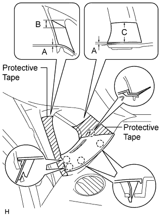 |
Put protective tape as shown in the illustration.
| Area | Specified Condition |
| A | 2.0 mm (0.079 in.) |
| B | 10.0 mm (0.394 in.) |
| C | 50.0 mm (1.969 in.) |
Attach the 5 claws to install the corner piece.
| 12. INSTALL FRONT PILLAR GARNISH CORNER PIECE RH |
| 13. INSTALL NO. 1 INSTRUMENT PANEL SPEAKER PANEL SUB-ASSEMBLY (w/ JBL Sound System) |
| 14. INSTALL GLOVE COMPARTMENT DOOR |
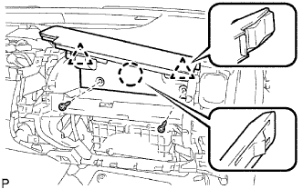 |
Attach the claw and 2 clips to install the glove compartment door.
Install the 2 screws.
| 15. INSTALL GLOVE COMPARTMENT DOOR ASSEMBLY |
Attach the 2 hinges to install the door.
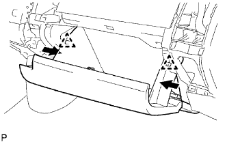 |
While pushing in the sides of the glove compartment door as indicated by the arrows in the illustration, engage it to the 2 stoppers.
| 16. INSTALL GLOVE COMPARTMENT DOOR STOPPER SUB-ASSEMBLY |
| 17. INSTALL MULTI-DISPLAY |
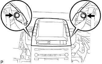 |
Connect the connector and install the multi-display.
Install the 2 bolts.
| 18. INSTALL NO. 2 INSTRUMENT PANEL REGISTER ASSEMBLY |
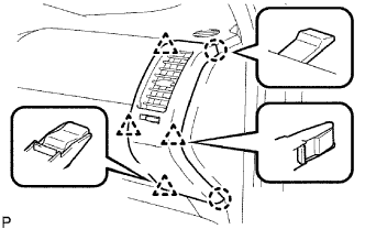 |
Attach the 2 claws and 4 clips to install the instrument panel register.
| 19. INSTALL NO. 4 INSTRUMENT PANEL REGISTER ASSEMBLY |
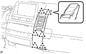 |
Attach the 6 clips to install the instrument panel register.
| 20. INSTALL NO. 3 INSTRUMENT PANEL REGISTER ASSEMBLY |
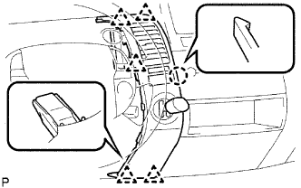 |
Connect the connector.
Attach the claw and 5 clips to install the instrument panel register.
| 21. INSTALL INSTRUMENT PANEL FINISH PANEL SUB-ASSEMBLY |
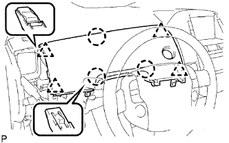 |
Connect the connector.
Attach the 3 claws and 4 clips to install the instrument panel finish panel.
| 22. INSTALL NO. 1 INSTRUMENT PANEL REGISTER ASSEMBLY |
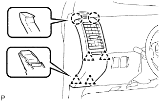 |
Attach the 2 claws and 4 clips to install the instrument panel register.
| 23. INSTALL COWL SIDE TRIM BOARD RH |
| 24. INSTALL COWL SIDE TRIM BOARD LH |
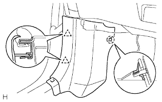 |
Attach the claw and 2 clips to install the trim board.
| 25. INSTALL FRONT DOOR INSIDE SCUFF PLATE LH |
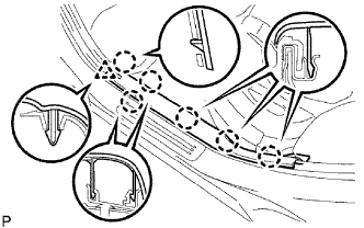 |
Attach the 6 claws and clip to install the scuff plate.
| 26. INSTALL FRONT DOOR INSIDE SCUFF PLATE RH |
| 27. INSTALL SPIRAL CABLE SUB-ASSEMBLY |
Check that the front wheels are facing straight ahead.
Set the turn signal switch to the neutral position.
Install the spiral cable.
Connect the connector to the spiral cable.
| 28. INSPECT SPIRAL CABLE SUB-ASSEMBLY |
Check that there are no scratches or cracks on its connector, and that the cable does not have cracks, dents or chipping.
| 29. INSTALL TURN SIGNAL SWITCH ASSEMBLY |
Install the turn signal switch to the steering column with the clamp.
| 30. INSTALL STEERING COLUMN COVER |
Engage the 4 claws to install the steering column upper cover and steering column lower cover.
| 31. INSTALL TILT LEVER BRACKET |
Install the tilt level bracket with the 2 screws.
| 32. INSPECT STEERING WHEEL CENTER POINT |
| 33. INSTALL STEERING WHEEL ASSEMBLY |
Align the matchmarks on the steering wheel and steering main shaft.
Install the steering wheel with the set nut.
| 34. INSTALL STEERING PAD ASSEMBLY |
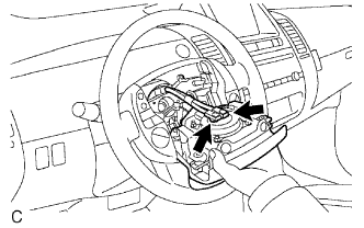 |
Support the steering pad with one hand as shown in the illustration.
Connect the 2 airbag connectors.
Connect the horn connector.
Install the steering pad after confirming that the circumference grooves of the screws are caught on the screw case.
Using a T30 "TORX" socket, install the 2 screws.
| 35. CONNECT CABLE TO BATTERY NEGATIVE TERMINAL |
| 36. INSPECT STEERING PAD ASSEMBLY |
Inspect the steering pad (Click here).
| 37. INSTALL NO. 3 STEERING WHEEL LOWER COVER |
| 38. INSTALL NO. 2 STEERING WHEEL LOWER COVER |
| 39. INSTALL REAR NO. 3 FLOOR BOARD ASSEMBLY |
| 40. INSTALL REAR DECK FLOOR BOX |
| 41. INSTALL REAR NO. 2 FLOOR BOARD |
| 42. INSPECT SRS WARNING LIGHT |
Inspect SRS warning light (Click here).
| 43. PERFORM CALIBRATION |
Perform calibration (Click here).