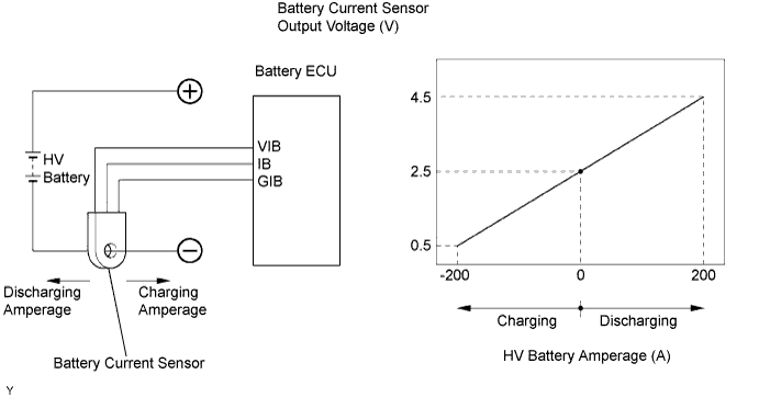
DTC P0ABF Hybrid Battery Pack Current Sensor Circuit |
DTC P0AC0 Hybrid Battery Pack Current Sensor Circuit Range/Performance |
DTC P0AC1 Hybrid Battery Pack Current Sensor Circuit Low |
DTC P0AC2 Hybrid Battery Pack Current Sensor Circuit High |
| DTC No. | DTC Detection Condition | Trouble Area |
| P0ABF | Power source of battery current sensor |
|
| P0AC0 | Battery current sensor malfunction |
|
| P0AC1 | Low voltage in battery current sensor |
|
| P0AC2 | High voltage in battery current sensor |
|
| Related DTCs | P0ABF |
| Related Sensor/Components (Main) | Battery temperature sensor |
| Related Sensor/Components (Related) | None |
| Frequency of Operation | Continuous |
| Duration | TOYOTA's intellectual property |
| MIL Operation | Immediate |
| Sequence of Operation | None |
| Related DTCs | P0AC0 |
| Related Sensor/Components (Main) | Battery temperature sensor |
| Related Sensor/Components (Related) | None |
| Frequency of Operation | Continuous |
| Duration | TOYOTA's intellectual property |
| MIL Operation | 2 driving cycles |
| Sequence of Operation | None |
| Related DTCs | P0AC1 |
| Related Sensor/Components (Main) | Battery temperature sensor |
| Related Sensor/Components (Related) | None |
| Frequency of Operation | Continuous |
| Duration | TOYOTA's intellectual property |
| MIL Operation | Immediate |
| Sequence of Operation | None |
| Related DTCs | P0AC2 |
| Related Sensor/Components (Main) | Battery temperature sensor |
| Related Sensor/Components (Related) | None |
| Frequency of Operation | Continuous |
| Duration | TOYOTA's intellectual property |
| MIL Operation | Immediate |
| Sequence of Operation | None |
| The monitor will run whenever the following DTCs are not present | TOYOTA's intellectual property |
| Other conditions belong to TOYOTA's intellectual property | - |
| Power-supply voltage for current sensor | Exceeds standard level |
| Sensor current | Exceeds standard level |
| Sensor voltage | Exceeds standard level |
| Sensor voltage | Exceeds standard level |
| Battery current sensor | DTC P0ABF, P0AC0, P0AC1 and P0AC2 are not detected |
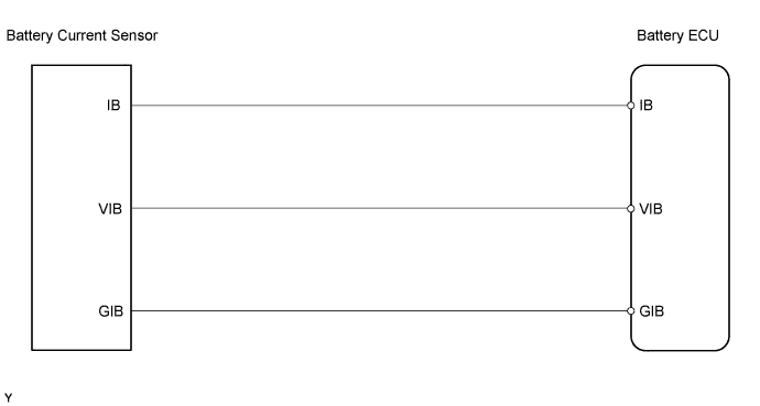
| 1.READ DTC OUTPUT (DTC P0A1F IS OUTPUT) |
Connect the Techstream to the DLC3.
Turn the power switch ON (IG) and the tester ON.
Enter the following menus: Powertrain / HV Battery / DTC.
Read DTCs.
|
| ||||
| NO | |
 |
| 2.CHECK WIRE HARNESS (BATTERY ECU - BATTERY CURRENT SENSOR) |
Turn the power switch OFF.
Remove the service plug grip (Click here).
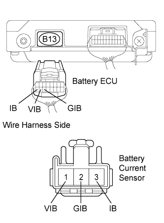 |
Disconnect the B13 battery ECU connector.
Disconnect the battery current sensor connector.
Turn the power switch ON (IG).
Measure the voltage of the battery ECU connector.
| Tester Connection | Specified Condition |
| B13-16 (IB) - Body ground | Below 1 V |
| B13-14 (GIB) - Body ground | Below 1 V |
| B13-15 (VIB) - Body ground | Below 1 V |
Turn the power switch OFF.
Measure the resistance of the wire harness side connectors.
| Tester Connection | Specified Condition |
| B13-16 (IB) - 3 (battery current sensor) | Below 1 Ω |
| B13-14 (GIB) - 2 (battery current sensor) | Below 1 Ω |
| B13-15 (VIB) - 1 (battery current sensor) | Below 1 Ω |
| B13-16 (IB) or 3 (battery current sensor) - Body ground | 10 kΩ or higher |
| B13-14 (GIB) or 2 (battery current sensor) - Body ground | 10 kΩ or higher |
| B13-15 (VIB) or 1 (battery current sensor) - Body ground | 10 kΩ or higher |
Reconnect the battery current sensor connector.
Reconnect the battery ECU connector.
Reinstall the service plug grip (Click here).
|
| ||||
| OK | |
|
| 3.REPLACE BATTERY CURRENT SENSOR |
Replace the battery current sensor (Click here).
Connect the Techstream to the DLC3.
Turn the power switch ON (IG) and the tester ON.
Enter the following menus: Powertrain / HV Battery / DTC.
Clear the DTCs and freeze frame data.
Perform a simulation test.
| NEXT | |
|
| 4.READ DTC OUTPUT (DTC P0ABF, P0AC0, P0AC1 AND P0AC2 IS NOT OUTPUT) |
Connect the Techstream to the DLC3.
Turn the power switch ON (IG) and the tester ON.
Enter the following menus: Powertrain / HV Battery / DTC.
Read DTCs.
|
| ||||
| YES | ||
 | ||
| ||
