Home › BRAKE › BRAKE CONTROL › ELECTRONICALLY CONTROLLED BRAKE SYSTEM

DTC    C1235/35    Foreign Object is Attached on Tip of Front Speed Sensor RH

DTC    C1236/36    Foreign Object is Attached on Tip of Front Speed Sensor LH

DTC    C1238/38    Foreign Object is Attached on Tip of Rear Speed Sensor RH

DTC    C1239/39    Foreign Object is Attached on Tip of Rear Speed Sensor LH

DTC    C1275/75    Abnormal Change in Output Signal of Front Speed Sensor RH (Test Mode DTC)

DTC    C1276/76    Abnormal Change in Output Signal of Front Speed Sensor LH (Test Mode DTC)

DTC    C1277/77    Abnormal Change in Output Signal of Rear Speed Sensor RH (Test Mode DTC)

DTC    C1278/78    Abnormal Change in Output Signal of Rear Speed Sensor LH (Test Mode DTC)

for Preparation Click here


DESCRIPTION


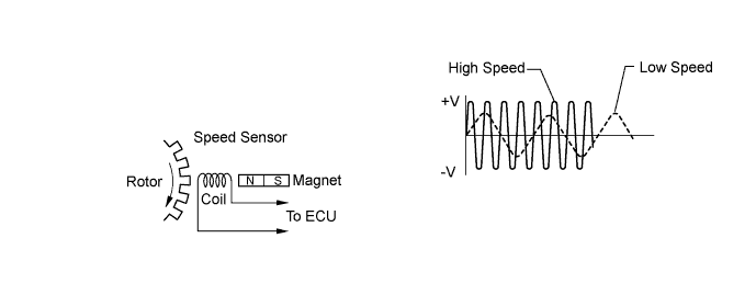
C108865E02

The speed sensor detects wheel speed and sends the appropriate signals to the ECU. These signals are used to control the ABS control system. The front and rear rotors have 48 serrations respectively.
When the rotors rotate, the magnetic field emitted by the permanent magnet in the speed sensor generates an AC voltage. Since the frequency of this AC voltage changes in direct proportion to the speed of the rotor, the frequency is used by the ECU to detect the speed of each wheel. When foreign matter adheres to the speed sensor tip or sensor rotor, or the rotor teeth are chipped, these DTCs are output. An abnormal waveform input from the sensor determines these conditions.
These DTCs may be detected when a malfunction occurs in the connector terminals or wire harness of the speed sensor circuit.
DTCs C1275/75, C1276/76, C1277/77 and C1278/78 can be deleted when the speed sensor sends a vehicle speed signal or the Test Mode ends. DTCs C1275/75, C1276/76, C1277/77 and C1278/78 are output only in the Test Mode.

DTC No.
INF Code
DTC Detection Condition
Trouble Area
C1235/35
302
Pulse waveform of speed sensor signal is abnormal for at least 5 sec. when vehicle speed is 20 km/h (12 mph) or more.
  1. Right front speed sensor
  2. Each speed sensor circuit
  3. Sensor installation
  4. Skid control ECU
C1236/36
303
Pulse waveform of speed sensor signal is abnormal for at least 5 sec. when vehicle speed is 20 km/h (12 mph) or more.
  1. Left front speed sensor
  2. Each speed sensor circuit
  3. Sensor installation
  4. Skid control ECU
C1238/38
304
Pulse waveform of speed sensor signal is abnormal for at least 5 sec. when vehicle speed is 20 km/h (12 mph) or more.
  1. Right rear speed sensor
  2. Each speed sensor circuit
  3. Skid control ECU
C1239/39
305
Pulse waveform of speed sensor signal is abnormal for at least 5 sec. when vehicle speed is 20 km/h (12 mph) or more.
  1. Left rear speed sensor
  2. Each speed sensor circuit
  3. Skid control ECU
C1275/75
C1276/76
-
Detected only during Test Mode
  1. Front speed sensor
  2. Front speed sensor circuit
  3. Sensor installation
C1275/77
C1276/78
-
Detected only during Test Mode
  1. Rear speed sensor
  2. Rear speed sensor circuit
  3. Sensor installation

HINT:
  1. DTC C1235/35 is for the right front speed sensor.
  2. DTC C1236/36 is for the left front speed sensor.
  3. DTC C1238/38 is for the right rear speed sensor.
  4. DTC C1239/39 is for the left rear speed sensor.


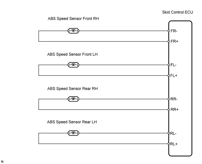
WIRING DIAGRAM


C126248E01


INSPECTION PROCEDURE

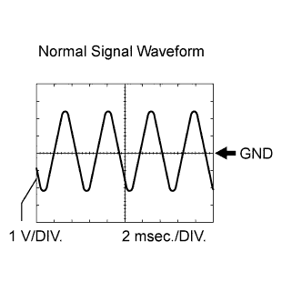
1.CHECK SPEED SENSOR AND SENSOR ROTOR SERRATIONS


    F100551E12
  1. Connect the oscilloscope to terminal FR+ and FR-, or FL+ and FL- of the skid control ECU.

  1. Drive the vehicle at approximately 30 km/h (19 mph), and check the signal waveform.

    OK:
    A waveform as shown should be output.

    1. As the vehicle speed (wheel revolution speed) increases, a cycle of the waveform narrows and the fluctuation in the output voltage becomes greater.
    2. When noise is identified in the waveform on the oscilloscope, error signals are generated due to the speed sensor rotor's scratches, looseness or foreign matter deposited on it.


NG
Go to step 4
OK


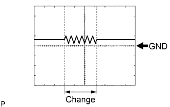
2.CHECK SPEED SENSOR AND SENSOR ROTOR SERRATIONS


    F047503E01
  1. Connect the oscilloscope to terminal FR+ and FR-, or FL+ and FL- of the skid control ECU.

  1. Check if the oscilloscope has any change when the wire harness connector is subject to vibration while the vehicle is stopped and the power switch is ON (IG). (If the connector is poorly connected, vibration of the wire harness connector may cause a temporary stop in current flow.)

    OK:
    There is no change in a waveform.


NG
REPAIR OR REPLACE HARNESS AND CONNECTOR
OK


3.RECONFIRM DTC
  1. Clear the DTCs (Click here ).

  1. Turn the power switch ON (READY).

  1. Check the same DTCs are recorded (Click here).
    Result 
    Result
    Proceed to
    DTC is not output
    A
    DTC is output
    B


B
REPLACE SKID CONTROL ECU
A

PROCEED TO NEXT CIRCUIT INSPECTION SHOWN IN PROBLEM SYMPTOMS TABLE 

4.INSPECT SPEED SENSOR TIP
  1. Remove the front axle hub and front speed sensor.

  1. Check the sensor tip.

    OK:
    No scratches or foreign matter on the sensor tip.

    NOTICE:
    Check the speed sensor signal after the replacement (Click here).


NG
CLEAN OR REPLACE SPEED SENSOR
OK


5.INSPECT SPEED SENSOR ROTOR
  1. Remove the front axle hub and front speed sensor rotor.

  1. Check the sensor rotor serrations.

    OK:
    No scratches, missing teeth or foreign matter on the rotors.

    HINT:
    If there is foreign matter in the rotor, remove it and check the output waveform after reassembly.

    NOTICE:
    Check the speed sensor signal after the replacement (Click here).


NG
CLEAN OR REPLACE SPEED SENSOR ROTOR
OK

REPLACE SPEED SENSOR