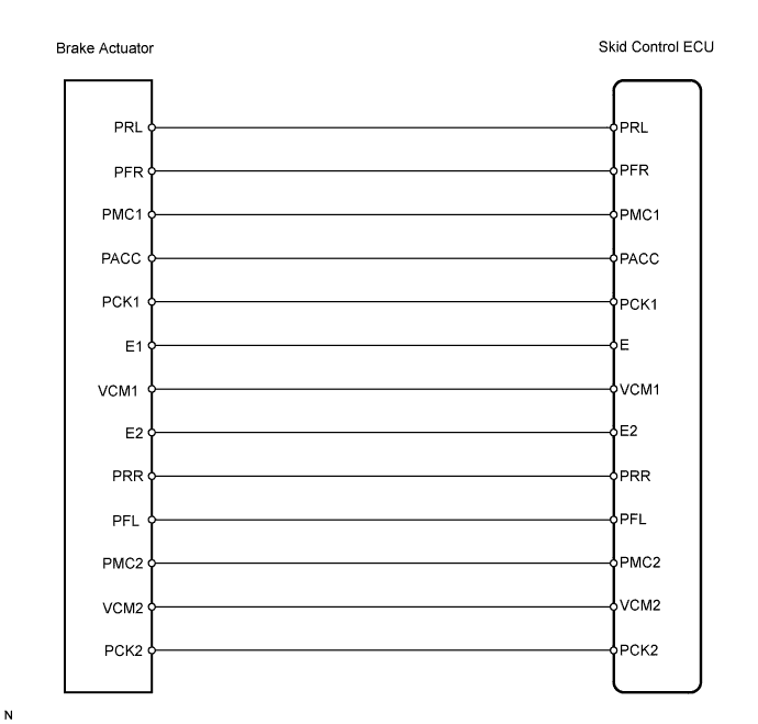
DTC C1246/46 Master Cylinder Pressure Sensor Malfunction |
DTC C1281/81 Master Cylinder Pressure Sensor Output Malfunction (Test Mode DTC) |
DTC C1364/61 Wheel Cylinder Pressure Sensor Malfunction |
| DTC No. | INF Code | DTC Detection Condition | Trouble Area |
| C1246/46 | 191 | Sensor power source 1 (VCM1) voltage is less than 4.7 V or 5.3 V or more for at least 0.05 sec. |
|
| C1246/46 | 192 | Ratio of master pressure sensor output voltage 1 (PMC1) to sensor power source (VCM1) is less than 5% or 90.5% or more for at least 0.05 sec. |
|
| C1246/46 | 194 | Sensor power source 2 (VCM2) voltage is less than 4.7 V or 5.3 V or more for at least 0.05 sec. |
|
| C1246/46 | 195 | Ratio of master pressure sensor output voltage 2 (PMC2) to sensor power source (VCM2) is less than 5% or 90.5% or more for at least 0.05 sec. |
|
| C1246/46 | 197 | Master pressure sensor output voltage 1 (PMC1) is abnormal. |
|
| C1246/46 | 198 | Master pressure sensor output voltage 2 (PMC2) is abnormal. |
|
| C1246/46 | 199 | Master pressure sensor output 1 (PMC1) is not approx. 0 Mpa when not braking. |
|
| C1246/46 | 200 | Master pressure sensor output 2 (PMC2) is not approx. 0 Mpa when not braking. |
|
| C1246/46 | 201 | PMC1 and PMC2 voltages are different when braking. |
|
| C1246/46 | 202 | Master pressure sensor 1 data (PMC1) is invalid. |
|
| C1246/46 | 205 | Master pressure sensor 2 data (PMC2) is invalid. |
|
| C1281/81 | - | Detected only during Test Mode. |
|
| C1364/61 | 221 | Sensor power source 1 (VCM1) voltage is less than 4.7 V or 5.3 V or more for at least 0.05 sec. |
|
| C1364/61 | 222 | Ratio of FR right sensor output voltage (PFR) to sensor power source (VCM1) is less than 5% or 90.5% or more for at least 0.05 sec. |
|
| C1364/61 | 224 | When one of following conditions is met:
|
|
| C1364/61 | 225 | Ratio of FR right sensor output voltage (PFR) to sensor power source (VCM1) is less than 90.5% for at least 0.1 sec. when self-diagnosis signal is output. |
|
| C1364/61 | 226 | Voltage difference before and after changing the pull-up resistance in the sensor signal input circuit is 0.3 V or more (poor connection). |
|
| C1364/61 | 227 | Sensor power source 2 (VCM2) voltage is less than 4.7 V or 5.3 V or more for at least 0.05 sec. |
|
| C1364/61 | 228 | Ratio of FR left sensor output voltage (PFL) to sensor power source (VCM2) is less than 5% or 90.5% or more for at least 0.05 sec. |
|
| C1364/61 | 230 | When one of following conditions is met:
|
|
| C1364/61 | 231 | Ratio of FR left sensor output voltage (PFL) to sensor power source (VCM2) is less than 90.5% for at least 0.1 sec. when self-diagnosis signal is output. |
|
| C1364/61 | 232 | Voltage difference before and after changing the pull-up resistance in the sensor signal input circuit is 0.3 V or more (poor connection). |
|
| C1364/61 | 233 | Sensor power source 2 (VCM2) voltage is less than 4.7 V or 5.3 V or more for at least 0.05 sec. |
|
| C1364/61 | 234 | Ratio of RR right sensor output voltage (PRR) to sensor power source (VCM2) is less than 5% or 90.5% or more for at least 0.05 sec. |
|
| C1364/61 | 236 | When one of following conditions is met:
|
|
| C1364/61 | 237 | Ratio of RR right sensor output voltage (PRR) to sensor power source (VCM2) is less than 90.5% for at least 0.1 sec. when self-diagnosis signal is output. |
|
| C1364/61 | 238 | Voltage difference before and after changing the pull-up resistance in the sensor signal input circuit is 0.3 V or more (poor connection). |
|
| C1364/61 | 239 | Sensor power source (VCM1) voltage is less than 4.7 V or 5.3 V or more for at least 0.05 sec. |
|
| C1364/61 | 240 | Ratio of RR left sensor output voltage (PRL) to sensor power source (VCM1) is less than 5% or 90.5% or more for at least 0.05 sec. |
|
| C1364/61 | 242 | When one of following conditions is met:
|
|
| C1364/61 | 243 | Ratio of RR left sensor output voltage (PRL) to sensor power source (VCM1) is less than 90.5% for at least 0.1 sec. when self-diagnosis signal is output. |
|
| C1364/61 | 244 | Voltage difference before and after changing the pull-up resistance in the sensor signal input circuit is 0.3 V or more (poor connection). |
|
| 1.CHECK WIRE HARNESS (SKID CONTROL ECU - BRAKE ACTUATOR) |
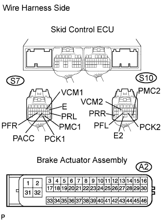 |
Disconnect the S7 and S10 ECU connectors.
Disconnect the A2 actuator connector.
Measure the resistance of the wire harness side connectors.
| Tester Connection | Specified Condition |
| S7-8 (E) - A2-45 (E1) | Below 1 Ω |
| S7-9 (VCM1) - A2-35 (VCM1) | Below 1 Ω |
| S7-18 (PRL) - A2-36 (PRL) | Below 1 Ω |
| S7-21 (PACC) - A2-46 (PACC) | Below 1 Ω |
| S7-23 (PFR) - A2-34 (PFR) | Below 1 Ω |
| S7-30 (PMC1) - A2-38 (PMC1) | Below 1 Ω |
| S7-31 (PCK1) - A2-37 (PCK1) | Below 1 Ω |
| S10-14 (VCM2) - A2-40 (VCM2) | Below 1 Ω |
| S10-21 (PCK2) - A2-42 (PCK2) | Below 1 Ω |
| S10-23 (PFL) - A2-39 (PFL) | Below 1 Ω |
| S10-27 (PMC2) - A2-43 (PMC2) | Below 1 Ω |
| S10-29 (E2) - A2-44 (E2) | Below 1 Ω |
| S10-31 (PRR) - A2-41 (PRR) | Below 1 Ω |
| S7-8 (E) - Body ground | 10 kΩ or higher |
| S7-9 (VCM1) - Body ground | 10 kΩ or higher |
| S7-18 (PRL) - Body ground | 10 kΩ or higher |
| S7-21 (PACC) - Body ground | 10 kΩ or higher |
| S7-23 (PFR) - Body ground | 10 kΩ or higher |
| S7-30 (PMC1) - Body ground | 10 kΩ or higher |
| S7-31 (PCK1) - Body ground | 10 kΩ or higher |
| S10-14 (VCM2) - Body ground | 10 kΩ or higher |
| S10-21 (PCK2) - Body ground | 10 kΩ or higher |
| S10-27 (PMC2) - Body ground | 10 kΩ or higher |
| S10-29 (E2) - Body ground | 10 kΩ or higher |
| S10-31 (PRR) - Body ground | 10 kΩ or higher |
|
| ||||
| OK | |
 |
| 2.CHECK SKID CONTROL ECU |
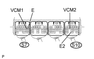 |
Measure the voltage of the connectors.
| Tester Connection | Condition | Specified Condition |
| S7-9 (VCM1) - Body ground | Power switch ON (READY) | 4.75 to 5.25 V |
| S10-14 (VCM2) - Body ground | Power switch ON (READY) | 4.75 to 5.25 V |
Measure the resistance of the connectors.
| Tester Connection | Specified Condition |
| S7-8 (E) - Body ground | Below 1 Ω |
| S10-29 (E2) - Body ground | Below 1 Ω |
|
| ||||
| OK | |
|
| 3.READ VALUE OF TECHSTREAM (MASTER CYLINDER PRESSURE SENSOR) |
Check the Data List for proper functioning of the master cylinder pressure sensor.
| Tester Display | Measurement Item/Range | Normal Condition | Diagnostic Note |
| Master Cylinder Sensor 1 | Master cylinder pressure sensor 1 reading / Min.: 0 V, Max.: 5 V | When brake pedal is released: 0.3 to 0.9 V | Reading increases when brake pedal is depressed |
| Master Cylinder Sensor 2 | Master cylinder pressure sensor 2 reading / Min.: 0 V, Max.: 5 V | When brake pedal is released: 0.3 to 0.9 V | Reading increases when brake pedal is depressed |
|
| ||||
| OK | |
|
| 4.READ VALUE OF TECHSTREAM (WHEEL CYLINDER PRESSURE SENSOR) |
Connect the pedal effort gauge.
Install the LSPV gauge (SST) and bleed air (Click here).
Select the Data List mode on Techstream.
| Tester Display | Measurement Item/Range | Normal Condition | Diagnostic Note |
| FR Wheel Cylinder | Front right pressure sensor / Min.: 0 V, Max.: 5 V | When brake pedal is released: 0.3 to 0.9 V | - |
| FL Wheel Cylinder | Front left pressure sensor / Min. 0 V, Max.: 5 V | When brake pedal is released: 0.3 to 0.9 V | - |
| RR Wheel Cylinder | Rear right pressure sensor / Min.: 0 V, Max.: 5 V | When brake pedal is released: 0.3 to 0.9 V | - |
| RL Wheel Cylinder | Rear left pressure sensor / Min. 0 V, Max.: 5 V | When brake pedal is released: 0.3 to 0.9 V | - |
Check the output value of the wheel cylinder pressure sensor at each fluid pressure during the Electronically Controlled Brake control.
| Fluid Pressure | FR Wheel Cylinder (Data List) | FL Wheel Cylinder (Data List) |
| 1 MPa (10.2 kgf/cm2, 145.0 psi) | 0.65 to 0.75 V | 0.65 to 0.75 V |
| 3 MPa (30.6 kgf/cm2, 435.2 psi) | 1.05 to 1.2 V | 1.05 to 1.2 V |
| 7 MPa (71.4 kgf/cm2, 1015.5 psi) | 1.8 to 2.05 V | 1.8 to 2.05 V |
| 10 MPa (102.0 kgf/cm2, 1450.7 psi) | 2.4 to 2.7 V | 2.4 to 2.7 V |
| Fluid Pressure | RR Wheel Cylinder (Data List) | RL Wheel Cylinder (Data List) |
| 1 MPa (10.2 kgf/cm2, 145.0 psi) | 0.65 to 0.75 V | 0.65 to 0.75 V |
| 3 MPa (30.6 kgf/cm2, 435.2 psi) | 1.05 to 1.2 V | 1.05 to 1.2 V |
|
| ||||
| OK | ||
 | ||
| ||
