BRAKE ACTUATOR > ON-VEHICLE INSPECTION |
| 1. INSPECT BRAKE ACTUATOR OPERATION |
Pre-check preparation
Move the shift lever to the P position. Apply the parking brake and connect the Techstream to the DLC3.
Turn the power switch ON (IG).
Turn on the Techstream. Select "Master Cylinder Sensor", "Master Cylinder Sensor 2", "FR W/C SensorS", "FL W/C Sensor", "RR W/C Sensor" and "RL W/C Sensor".
Check FR system solenoid (SLA**, SLR**, SMC1, SMC2)
Select "SLAFR CUR". → Set the current to 1.2 A. → Check the output voltage.
| Sensor | 10 to 20 sec. after check start (V) | 35 sec. or more after check start (V) |
| Master Cylinder Sensor | 0.3 to 0.7 | 0.3 to 0.7 |
| Master Cylinder Sensor 2 | 0.3 to 0.7 | 0.3 to 0.7 |
| FR W/C Sensor | 2.5 to 4.5 | 0.3 to 0.7 |
| FL W/C Sensor | 0.3 to 0.7 | 0.3 to 0.7 |
| RR W/C Sensor | 0.3 to 0.7 | 0.3 to 0.7 |
| RL W/C Sensor | 0.3 to 0.7 | 0.3 to 0.7 |
Check FL system solenoid (SLA**, SLR**, SMC1, SMC2)
Select "SLAFL CUR". → Set the current to 1.2 A. → Check the output voltage.
| Sensor | 10 to 20 sec. after check start (V) | 35 sec. or more after check start (V) |
| Master Cylinder Sensor | 0.3 to 0.7 | 0.3 to 0.7 |
| Master Cylinder Sensor 2 | 0.3 to 0.7 | 0.3 to 0.7 |
| FR W/C Sensor | 0.3 to 0.7 | 0.3 to 0.7 |
| FL W/C Sensor | 2.5 to 4.5 | 0.3 to 0.7 |
| RR W/C Sensor | 0.3 to 0.7 | 0.3 to 0.7 |
| RL W/C Sensor | 0.3 to 0.7 | 0.3 to 0.7 |
Check RR system solenoid (SLA**, SLR**, SMC1, SMC2)
Select "SLARR CUR". → Set the current to 1.2 A. → Check the output voltage.
| Sensor | 10 to 20 sec. after check start (V) | 35 sec. or more after check start (V) |
| Master Cylinder Sensor | 0.3 to 0.7 | 0.3 to 0.7 |
| Master Cylinder Sensor 2 | 0.3 to 0.7 | 0.3 to 0.7 |
| FR W/C Sensor | 0.3 to 0.7 | 0.3 to 0.7 |
| FL W/C Sensor | 0.3 to 0.7 | 0.3 to 0.7 |
| RR W/C Sensor | 2.5 to 4.5 | 0.3 to 0.7 |
| RL W/C Sensor | 0.3 to 0.7 | 0.3 to 0.7 |
Check RL system solenoid (SLA**, SLR**, SMC1, SMC2)
Select "SLARL CUR". → Set the current to 1.2 A. → Check the output voltage.
| Sensor | 10 to 20 sec. after check start (V) | 35 sec. or more after check start (V) |
| Master Cylinder Sensor | 0.3 to 0.7 | 0.3 to 0.7 |
| Master Cylinder Sensor 2 | 0.3 to 0.7 | 0.3 to 0.7 |
| FR W/C Sensor | 0.3 to 0.7 | 0.3 to 0.7 |
| FL W/C Sensor | 0.3 to 0.7 | 0.3 to 0.7 |
| RR W/C Sensor | 0.3 to 0.7 | 0.3 to 0.7 |
| RL W/C Sensor | 2.5 to 4.5 | 0.3 to 0.7 |
Check SMC1, SMC2
Select and enter "ELECTRONICALLY CONTROLLED BRAKE SYSTEM INVALID" to prohibit the brake control (ELECTRONICALLY CONTROLLED BRAKE SYSTEM) on the Techstream menu screen.
Check that the ELECTRONICALLY CONTROLLED BRAKE SYSTEM warning light comes on.
Check the output voltage by depressing the brake pedal.
| Sensor | Specified Condition |
| Between "Master Cylinder Sensor" and "FR W/C Sensor" | Less than 0.4 V |
| Between "Master Cylinder Sensor 2" and "FL W/C Sensor" | Less than 0.4 V |
Press the return key on the Techstream and cancel brake control prohibition (ELECTRONICALLY CONTROLLED BRAKE SYSTEM INVALID).
| 2. INSPECT PRESSURE SENSOR OPERATION |
Check battery voltage.
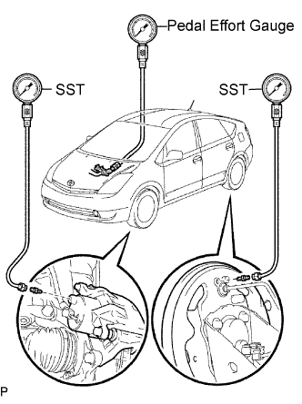
Connect the hydro booster pressure gauge and pedal effort gauge.
![]() |
Install the LSPV gauge (SST) and brake pedal effort gauge.
Bleed the air out of the hydro booster pressure gauge.
Move the shift lever to the P position. Connect the Techstream to the DLC3 with the parking brake applied.
Turn the power switch ON (IG).
Clear the DTC (Click here).
Check wheel cylinder pressure sensor and master pressure sensor.
Turn on the Techstream. Select "Master Cylinder Sensor", "Master Cylinder Sensor 2", "FR W/C Sensor", "FL W/C Sensor", "RR W/C Sensor" and "RL W/C Sensor".
Check the brake effort, pressure gauge reading, and output pressure voltage.
If incorrect, troubleshoot the brake system (Click here).
| Brake effort N (kgf, lbf) | Master Cylinder Sensor (V) | Master Cylinder Sensor 2 (V) |
| 200 (20.4, 45) | 0.9 to 1.2 | 0.9 to 1.2 |
| 500 (51, 112) | 1.7 to 2.2 | 1.7 to 2.2 |
| Brake effort N (kgf, lbf) | Front right wheel hydraulic pressure MPa (kgf/cm2, psi) | FR W/C Sensor (V) |
| 50 (5.1, 11) | 3.6 (36.4, 518) | 1.15 to 1.35 |
| 100 (10.2, 22) | 6.9 (70.0, 996) | 1.8 to 2.0 |
| 150 (15.3, 34) | 9.1 (93.3, 1,327) | 2.25 to 2.45 |
| 200 (20.4, 45) | 11.4 (115.9, 1,648) | 2.65 to 2.95 |
| Brake effort N (kgf, lbf) | Front left wheel hydraulic pressure MPa (kgf/cm2, psi) | FL W/C Sensor (V) |
| 50 (5.1, 11) | 3.6 (36.4, 518) | 1.15 to 1.35 |
| 100 (10.2, 22) | 6.9 (70.0, 996) | 1.8 to 2.0 |
| 150 (15.3, 34) | 9.1 (93.3, 1,327) | 2.25 to 2.45 |
| 200 (20.4, 45) | 11.4 (115.9, 1,648) | 2.65 to 2.95 |
| Brake effort N (kgf, lbf) | Rear right wheel hydraulic pressure MPa (kgf/cm2, psi) | RR W/C Sensor (V) |
| 50 (5.1, 11) | 3.9 (39.4, 560) | 1.2 to 1.4 |
| 100 (10.2, 22) | 4 (40.8, 580) | 1.25 to 1.5 |
| 150 (15.3, 34) | 4 (40.8, 580) | 1.25 to 1.5 |
| 200 (20.4, 45) | 4 (40.8, 580) | 1.25 to 1.5 |
| Brake effort N (kgf, lbf) | Rear left wheel hydraulic pressure MPa (kgf/cm2, psi) | RL W/C Sensor (V) |
| 50 (5.1, 11) | 3.9 (39.4, 560) | 1.2 to 1.4 |
| 100 (10.2, 22) | 4 (40.8, 580) | 1.25 to 1.5 |
| 150 (15.3, 34) | 4 (40.8, 580) | 1.25 to 1.5 |
| 200 (20.4, 45) | 4 (40.8, 580) | 1.25 to 1.5 |
Check accumulator Sensor.
Move the shift lever to the P position. Apply the parking brake and connect the Techstream.
Turn the power switch ON (IG).
Turn on the Techstream. Select and enter the Accumulator Sensor.
Temporarily operate the pump motor by depressing the brake pedal 4 to 5 times.
After confirming that the pump motor stops, check the pressure output voltage.
If incorrect, troubleshoot the brake system (Click here).