Home › BRAKE › BRAKE CONTROL › ELECTRONICALLY CONTROLLED BRAKE SYSTEM

DTC    C1210/36    Zero Point Calibration of Yaw Rate Sensor Undone

DTC    C0371/71    Yaw Rate Sensor (Test Mode DTC)

DTC    C1232/32    Stuck in Acceleration Sensor

DTC    C1234/34    Yaw Rate Sensor Malfunction

DTC    C1243/43    Acceleration Sensor Stuck Malfunction

DTC    C1244/44    Open or Short in Acceleration Sensor Circuit

DTC    C1245/45    Acceleration Sensor Output Malfunction

DTC    C1279/79    Acceleration Sensor Output Voltage Malfunction (Test Mode DTC)

DTC    C1336/39    Zero Point Calibration of Acceleration Sensor Undone

DTC    C1381/97    Acceleration Sensor Power Supply Voltage Malfunction

for Preparation Click here


DESCRIPTION

The yaw rate (deceleration) sensor detects any gravity applied to the vehicle and transmit the signal to the skid control ECU via CAN communication system (vehicle equipped with Enhanced VSC). The deceleration sensor is built into the yaw rate sensor and detects the vehicle condition in the 2 systems (GL1, GL2).
When a malfunction occurs in the communication line with the yaw rate sensor, DTC U0123/62 (yaw rate sensor communication malfunction) and DTC U0124/95 (deceleration sensor communication malfunction) are output.
DTCs C0371/71 and C1279/79 are deleted when the yaw rate and deceleration sensor sends a yaw rate and/or deceleration signal or Test Mode ends. DTCs C0371/71 and C1279/79 are output only in Test Mode.

DTC No.
NF Code
DTC Detection Condition
Trouble Area
C1210/36
336
Yaw rate sensor zero point calibration is unfinished.
Zero point calibration undone (Perform zero point calibration and check DTC. If DTC is not output again, the sensor is normal.)
C0731/71
-
Detected only during Test Mode
  1. Yaw rate (deceleration) sensor
  2. Yaw rate (deceleration) sensor circuit
C1232/32
311
312
One GL1/2 signal fluctuation is within 80 mV and the other is 1.9 V or more for at least 30 sec. when vehicle speed is 10 km/h (6 mph)
  1. Yaw rate (deceleration) sensor
  2. Skid control ECU
C1234/34
331
332
333
334
335
337
Signal of malfunction that is detected at sensor self-check is received when communication with the sensors is valid.
Yaw rate (deceleration) sensor
C1243/43
317
Sensor sticking can be seen 16 times or more in a series at a speed between 30 km/h (18 mph) and 0 km/h (0 mph).
  1. Yaw rate (deceleration) sensor
  2. Skid control ECU
C1244/44
314
Difference between GL1 and GL2 is not less than 0.4 G for at least 60 sec. after the difference is 0.6 G or more when the vehicle speed is 0 km/h (0 mph).
Malfunction signal from deceleration sensor is received.
  1. Yaw rate (deceleration) sensor
  2. Yaw rate (deceleration) sensor installation
  3. Zero point calibration not done
  4. Skid control ECU
C1245/45
313
Difference between the G value calculated from deceleration sensor value and vehicle speed exceeds 0.35 G for at least 60 sec. when vehicle speed is 30 km/h (18 mph).
  1. Yaw rate (deceleration) sensor
  2. Yaw rate (deceleration) sensor installation
  3. Zero point calibration not done
  4. Skid control ECU
C1279/79
-
Detected only during Test Mode
  1. Yaw rate (deceleration) sensor
  2. Yaw rate (deceleration) sensor circuit
C1336/39
318
Vehicle speed increases with unfinished zero point calibration.
Zero point calculation is not within specified range when zero point calibration is finished.
Zero point calibration undone (Perform zero point calibration and check DTC. If DTC is not output again, the sensor is normal.)
C1381/97
315
Power source voltage is not within specified range when communication between skid control ECU and sensor is valid.
  1. Yaw rate (deceleration) sensor circuit
  2. Harness and connector
  3. Skid control ECU

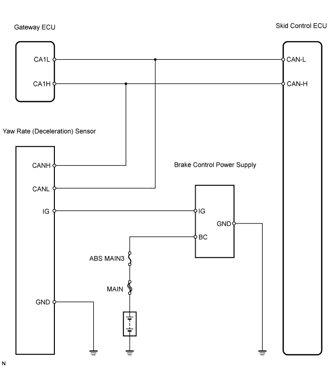
WIRING DIAGRAM


C126246E02


INSPECTION PROCEDURE

1.CHECK DTC
  1. Clear the DTCs (Click here).

  1. Turn the power switch ON (READY).

  1. Check that the trouble code for CAN communication DTCs U0073/94 and U0123/62 are not output.
    Result 
    Result
    Proceed to
    CAN communication DTCs are not output.
    A
    CAN communication DTC U0073 or U0123/62 is output.
    B
    Only unfinished zero point calibration DTC C1210/36 or C1336/36 is output.
    C


B
REPAIR CIRCUIT INDICATED BY OUTPUT CODE

C
Go to step 5
A


2.CHECK SENSOR INSTALLATION (YAW RATE (DECELERATION) SENSOR)
  1. Check that the yaw rate (deceleration) sensor has been installed properly.

    OK:
    The sensor should be tightened to the specified torque.
    The sensor should not be tilted.


NG
INSTALL YAW RATE SENSOR CORRECTLY
OK


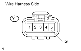
3.CHECK WIRE HARNESS (YAW RATE SENSOR - BATTERY)


    F045082E10
  1. Disconnect the Y1 sensor connector.

  1. Turn the power switch ON (READY).

  1. Measure the voltage of the wire harness side connector.

    Standard voltage:
    Tester Connection
    Specified Condition
    Y1-5 (IG) - Body ground
    10 to 14 V


NG
REPAIR OR REPLACE HARNESS AND CONNECTOR
OK


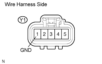
4.CHECK WIRE HARNESS (YAW RATE SENSOR - BODY GROUND)


    F045082E12
  1. Disconnect the Y1 sensor connector.

  1. Measure the resistance of the wire harness side connector.

    Standard resistance:
    Tester Connection
    Specified Condition
    Y1-1 (GND) - Body ground
    Below 1 Ω


NG
REPAIR OR REPLACE HARNESS AND CONNECTOR
OK

REPLACE YAW RATE SENSOR 

5.PERFORM ZERO POINT CALIBRATION OF YAW RATE SENSOR AND DECELERATION SENSOR
  1. Perform the zero point calibration of the yaw rate (deceleration) sensor (Click here).


NEXT


6.RECONFIRM DTC
  1. Clear the DTCs (Click here).

  1. Turn the power switch ON (READY).

  1. Check the same DTCs are recorded (Click here).
    Result 
    Result
    Proceed to
    DTC is not output
    A
    DTC is output
    B

    HINT:
    This DTC may be memorized due to a malfunction in the connector terminal.


B
REPLACE YAW RATE SENSOR
A

END