Home › BRAKE › BRAKE CONTROL › ELECTRONICALLY CONTROLLED BRAKE SYSTEM

DTC    C1231/31    Steering Angle Sensor Circuit Malfunction

for Preparation Click here


DESCRIPTION

The skid control ECU inputs the steering sensor signal through the CAN communication. When a malfunction occurs in the communication line with the steering sensor, DTC U0126/63 (malfunction in communication with steering angle sensor) is output.

DTC No.
INF Code
DTC Detection Condition
Trouble Area
C1231/31
341
342
343
344
345
346
347
348
349
When either condition below is met:
  1. Steering angle sensor malfunction signal is received when data transmission is valid (internal malfunction is detected at sensor self-check).
  2. A signal of +B open in steering angle sensor is received when communication with sensor is valid.
  1. Steering angle sensor
  2. Skid control ECU

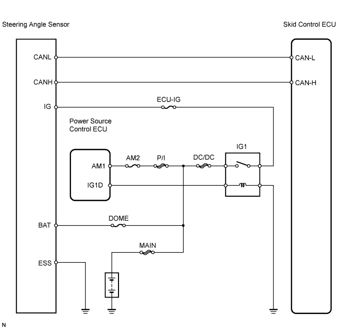
WIRING DIAGRAM


C153493E02


INSPECTION PROCEDURE

NOTICE:
When replacing the skid control ECU, perform initialization of linear solenoid valve and calibration (Click here).

HINT:
  1. When U0126 is output together with C1231/31, inspect and repair the trouble areas indicated by U0126/63 first.
  2. When the speed sensor or the yaw rate (deceleration) sensor has trouble, DTCs for the steering angle sensor may be output even when the steering angle sensor is normal. When DTCs for the speed sensor or yaw rate sensor are output together with other DTCs for the steering angle sensor, inspect and repair the speed sensor and yaw rate (deceleration) sensor first, and then inspect and repair the steering angle sensor.

1.CHECK HARNESS AND CONNECTOR (MOMENTARY INTERRUPTION)
  1. Using Techstream, check for any momentary interruption in the wire harness and connectors between the skid control ECU and steering angle sensor (Click here).

    ABS / VSC / TRAC: 
    Tester Display
    Measurement Item/Range
    Normal Condition
    Diagnostic Note
    Steering Open
    Steering sensor open detection / OPN-DET or NORMAL
    NORMAL: Normal condition
    -

    OK:
    There are no momentary interruptions.


NG
REPAIR OR REPLACE HARNESS AND CONNECTOR
OK


2.READ VALUE OF TECHSTREAM (STEERING ANGLE SENSOR)
  1. Check the Data List for proper functioning of the steering angle sensor.

    ABS / VSC / TRAC: 
    Tester Display
    Measurement Item/Range
    Normal Condition
    Diagnostic Note
    Steering Angle Sensor
    Steering sensor /
    Min.: -1152 deg/s, Max.: 1150.875 deg/s
    Left turn: Increase
    Right turn: Decrease
    -

    OK:
    Steering angle value should change.


OK
REPLACE SKID CONTROL ECU
NG


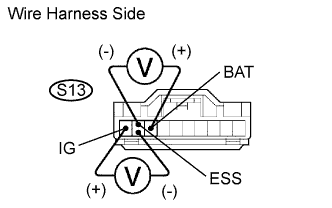
3.CHECK WIRE HARNESS (STEERING ANGLE SENSOR - BATTERY AND BODY GROUND)


    G026292E06
  1. Remove the steering wheel and the column lower cover.

  1. Disconnect the S13 sensor connector.

  1. Turn the power switch ON (READY).

  1. Measure the voltage of the wire harness side connector.

    Standard voltage:
    Tester Connection
    Specified Condition
    S13-1 (IG) - S13-2 (ESS)
    10 to 14 V
    S13-3 (BAT) - S13-2 (ESS)
    10 to 14 V


NG
REPAIR OR REPLACE HARNESS AND CONNECTOR
OK

REPLACE STEERING ANGLE SENSOR