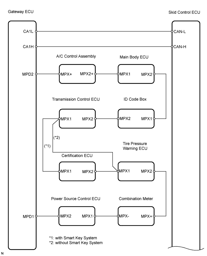
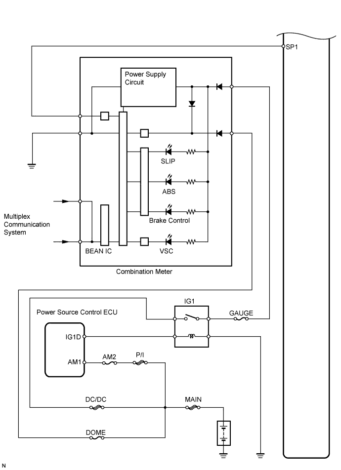
ELECTRONICALLY CONTROLLED BRAKE SYSTEM > Slip Indicator Light Circuit |
| 1.PERFORM ACTIVE TEST BY TECHSTREAM (SLIP INDICATOR LIGHT) |
Select the Active Test, generate a control command, and then check that the SLIP indicator light operates.
| Tester Display | Test Part | Control Range | Diagnostic Note |
| Slip Indicator Light | SLIP indicator light | Indicator light ON / OFF | Observe combination meter |
|
| ||||
| NG | |
 |
| 2.CHECK CAN COMMUNICATION SYSTEM |
Check if a CAN communication system DTC is output (Click here).
| Result | Proceed to |
| DTC is not output | A |
| DTC is output | B |
|
| ||||
| A | |
|
| 3.CHECK MULTIPLEX COMMUNICATION SYSTEM |
Check if a multiplex communication system DTC is output (Click here).
| Result | Proceed to |
| DTC is not output | A |
| DTC is output | B |
|
| ||||
| A | ||
 | ||
| ||
