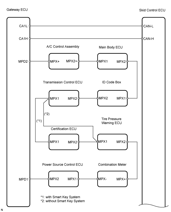
ELECTRONICALLY CONTROLLED BRAKE SYSTEM > Brake Warning Light Circuit |
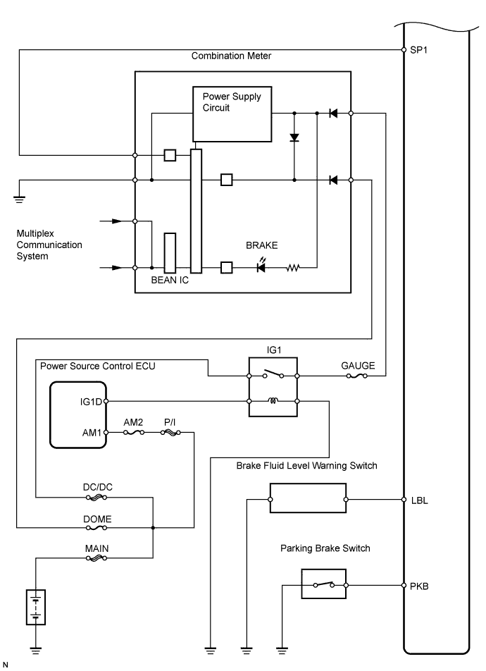
| 1.CHECK BRAKE FLUID LEVEL IN RESERVOIR |
Check that the brake fluid level is sufficient.
|
| ||||
| OK | |
 |
| 2.CHECK DTC FOR ABS |
Check if the DTCs are recorded (Click here).
|
| ||||
| NG | |
|
| 3.INSPECT PARKING BRAKE SWITCH ASSEMBLY |
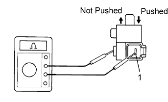 |
Remove the parking brake switch connector.
Measure the resistance of the switch.
| Tester Connection | Switch Condition | Specified Condition |
| P2-1 - Ground part | Not pushed | Below 1 Ω |
| P2-1 - Ground part | Pushed | 10 kΩ or higher |
|
| ||||
| OK | |
|
| 4.CHECK WIRE HARNESS (SKID CONTROL ECU - PARKING BRAKE SWITCH) |
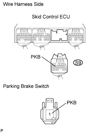 |
Disconnect the S9 ECU connector.
Disconnect the P2 switch connector.
Measure the resistance of the wire harness side connectors.
| Tester Connection | Specified Condition |
| S9-14 (PKB) - P2-1 (PKB) | Below 1 Ω |
| S9-14 (PKB) - Body ground | 10 kΩ or higher |
|
| ||||
| OK | |
|
| 5.INSPECT BRAKE FLUID LEVEL WARNING SWITCH |
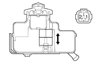 |
Remove the reservoir tank cap and strainer.
Disconnect the brake fluid level warning switch connector.
Measure the resistance of the switch.
| Tester Connection | Fluid Level | Specified Condition |
| B1-1 - B1-2 | Proper | 1.8 to 2.16 kΩ |
| B1-1 - B1-2 | Below minimum level | 10 kΩ or higher |
|
| ||||
| OK | |
|
| 6.INSPECT SKID CONTROL ECU CONNECTOR |
Check the skid control ECU connector's connecting condition.
|
| ||||
| OK | |
|
| 7.PERFORM ACTIVE TEST BY TECHSTREAM (BRAKE WARNING LIGHT) |
Select the Active Test, generate a control command, and then check that the brake warning light operates.
| Tester Display | Test Part | Control Range | Diagnostic Note |
| Brake Warning Light | BRAKE warning light | Warning light ON / OFF | Observe combination meter |
|
| ||||
| OK | ||
 | ||
| ||
