Components
| Functions
|
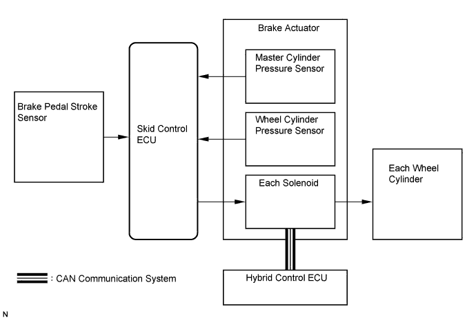
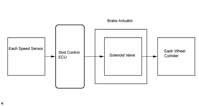
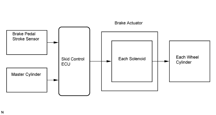
Skid control ECU*
| Calculates brake control in accordance with sensor / ECU signals or communication with hybrid ECU
|
Brake control power supply assembly*
| Charges capacitor inside unit and supplies power source to system by discharging when voltage of vehicle's power source drops
|
Speed sensor
| Detects speed of each wheel and inputs data into skid control ECU
|
Pedal stroke sensor*
| Detects brake pedal stroke and inputs data into skid control ECU
|
Yaw rate / deceleration sensor*
| Detects forward / rearward and lateral acceleration, and then inputs data into skid control ECU
|
Steering angle sensor
| Detects steering wheel angle and steering wheel direction, and then inputs data into skid control ECU
|
Accumulator
| Accumulates fluid pressure generated by pump
|
Accumulator pressure sensor (PACC)
| Detects accumulator pressure and inputs data into skid control ECU
|
Master cylinder
| Generates pressure according to pedal effort
|
Brake fluid reservoir
| Stores master cylinder system / power supply system brake fluid
Brake fluid level warning switch built into reservoir detects decrease of brake fluid
|
Stroke simulator
| Generates smooth pedal stroke in accordance with pedal effort during system control
|
Stroke simulator cut valve (SCSS)
| Changes intake / cutoff of brake fluid from master cylinder to stroke simulator
Sends oil pressure generated in master cylinder to stroke simulator during system control
Cuts brake fluid flow from master cylinder to stroke simulator when system is not controlling
|
Master cylinder pressure sensor 1 (PMC)
Master cylinder pressure sensor 2 (PMC2)
| Detects fluid pressure inside master cylinder and inputs data into skid control ECU
|
Relief valve
| Releases brake fluid into reservoir and prevents excessively high power supply system pressure when pump operates continuously due to malfunctions in parts such as accumulator oil pressure sensor
|
Wheel cylinder pressure sensor
| Detects pressure in each wheel cylinder and inputs data into skid control ECU
|
ABS NO. 1 relay
ABS NO. 2 relay
| Supplies power to each solenoid according to skid control ECU signals
Supplies power to skid control ECU
Supplies electricity and maintains operating condition for brake system when power switch is OFF
|
ABS MTR relay
ABS MTR 2 relay
| Supplies power to each motor according to skid control ECU signals
Drives relay 1 under normal condition and drives relay 2 under ABS operation
Substitutes relay operation when one relay malfunctions
|
Changeover solenoid valve (SMC1, SMC2)
| Changeover solenoid valve switches brake hydraulic pressure passage depending on whether system is in operation or not operation
|
Linear solenoid valve (SLA##, SLR##)
| Controls wheel cylinder hydraulic pressure according to regenerative braking force in order to generate braking force required by driver under normal brake operation
Controls hydraulic pressure of each wheel cylinder under ABS, VSC brake operation
SLA## adjusts pressure increase level
SLR## adjusts pressure decrease level
|
Stop light switch
| Illuminates brake light when brake pedal is depressed (sends brake ON signal to skid control ECU)
|
BRAKE warning light (Red)
| Informs driver that there is trouble with Electronically Controlled Brake (normal brake) by turning on
Informs driver when parking brake is applied and brake fluid level drops by turning on
|
BRAKE warning light ((Yellow) Brake control warning light)
| Informs driver when there is trouble with Electronically Controlled Brake or problem with brake system that has no influence on driving, by turning on
|
ABS warning light
| Informs driver that there is trouble with ABS by illuminating light
|
VSC warning light
| Informs driver that there is trouble with Enhanced VSC by illuminating light
|
SLIP indicator
| Informs driver that Enhanced VSC and ABS are operating by blinking light
|
Skid control buzzer
| Informs driver when there is trouble with hydraulic pressure source or power source by continuous buzzer sound
Informs that Enhanced VSC is operating by intermittent buzzer sound
|