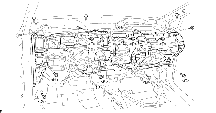
Install the 8 clips to the duct and lower instrument panel.
LOWER INSTRUMENT PANEL > INSTALLATION |
| 1. INSTALL LOWER INSTRUMENT PANEL SUB-ASSEMBLY |
Install the instrument panel.
Connect all the connectors and attach all the clamps.
Install the 2 screws.
Install the 6 bolts.
Install the 8 clips to the duct and lower instrument panel.
| 2. INSTALL SHIFT LEVER ASSEMBLY LOWER |
| 3. INSTALL POWER STEERING ECU |
| 4. INSTALL NO. 1 INSTRUMENT PANEL UNDER COVER SUB-ASSEMBLY |
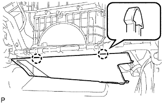 |
Attach the 2 claws to install the instrument panel under cover.
| 5. INSTALL INSTRUMENT PANEL FINISH PANEL LOWER |
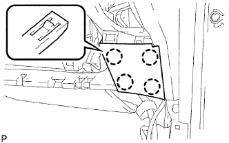 |
Attach the 4 claws to install the instrument panel finish panel.
| 6. INSTALL GLOVE COMPARTMENT DOOR LOCK ASSEMBLY |
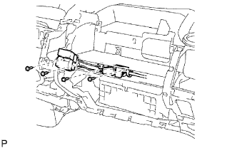 |
Install the glove compartment door lock with the 4 screws.
| 7. INSTALL GLOVE COMPARTMENT DOOR LOCK COVER |
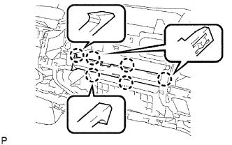 |
Attach the 6 claws to install the glove compartment door lock cover.
| 8. INSTALL INSTRUMENT PANEL FINISH PANEL LOWER CENTER |
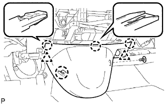 |
Attach the 4 claws and 2 clips to install the instrument panel finish panel.
Install the clip.
| 9. INSTALL RADIO RECEIVER |
| 10. INSTALL NO. 1 CENTER CLUSTER CUSHION |
| 11. INSTALL INSTRUMENT CLUSTER FINISH PANEL ASSEMBLY CENTER |
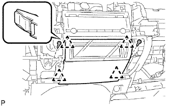 |
Attach the 4 claws and 2 clips to install the instrument cluster finish panel.
Install the 2 screws.
| 12. INSTALL COWL SIDE TRIM BOARD LH |
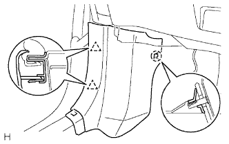 |
Attach the claw and 2 clips to install the trim board.
| 13. INSTALL COWL SIDE TRIM BOARD RH |
| 14. INSTALL FRONT DOOR SCUFF PLATE LH |
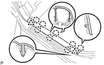 |
Attach the 8 claws and 2 clips to install the scuff plate.
| 15. INSTALL FRONT DOOR SCUFF PLATE RH |
| 16. INSTALL SPIRAL CABLE SUB-ASSEMBLY |
Check that the front wheels are facing straight ahead.
Set the turn signal switch to the neutral position.
Install the spiral cable.
Connect the connector to the spiral cable.
| 17. INSTALL STEERING COLUMN COVER |
Engage the 4 claws to install the steering column upper cover and steering column lower cover.
| 18. INSTALL TILT LEVER BRACKET |
Install the tilt level bracket with the 2 screws.
| 19. INSTALL STEERING WHEEL ASSEMBLY |
Align the matchmarks on the steering wheel and steering main shaft.
Install the steering wheel with the set nut.
| 20. INSTALL STEERING PAD ASSEMBLY |
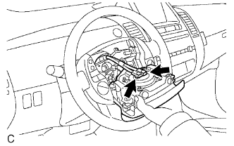 |
Support the steering pad with one hand as shown in the illustration.
Connect the 2 airbag connectors.
Connect the horn connector.
Install the steering pad after confirming that the circumference grooves of the screws are caught on the screw case.
Using a T30 "TORX" socket, install the 2 screws.
| 21. INSTALL NO. 3 STEERING WHEEL COVER LOWER |
| 22. INSTALL NO. 2 STEERING WHEEL COVER LOWER |
| 23. INSTALL INSTRUMENT PANEL SAFETY PAD |
Install the instrument panel (Click here).
| 24. CONNECT CABLE TO NEGATIVE BATTERY TERMINAL |
| 25. PERFORM INITIALIZATION |
Perform initialization (Click here).
| 26. CHECK SRS WARNING LIGHT |
Check the SRS warning light (Click here).