 |
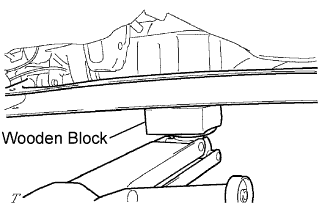
Support the rear axle beam with a jack. Insert a wooden block between the jack and the center of thee rear axle beam to prevent damage.
REAR AXLE BEAM > INSTALLATION |
| 1. TEMPORARILY TIGHTEN REAR AXLE BEAM ASSEMBLY |
|
Support the rear axle beam with a jack. Insert a wooden block between the jack and the center of thee rear axle beam to prevent damage.
Slowly raise the jack to install the rear axle beam on the vehicle. Insert the 2 bolts from the inner side of the vehicle and temporarily tighten them with the 2 nuts (1 nut and bolt each for the left and right sides).
| 2. TEMPORARILY TIGHTEN REAR SHOCK ABSORBER WITH COIL SPRING |
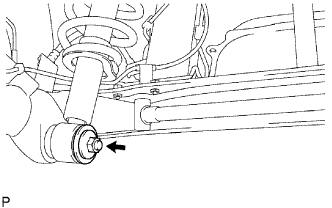 |
Install the left and right side rear shock absorber with coil spring (lower side) to the rear axle beam. Temporarily tighten the nuts.
| 3. INSTALL REAR AXLE HUB AND BEARING ASSEMBLY LH |
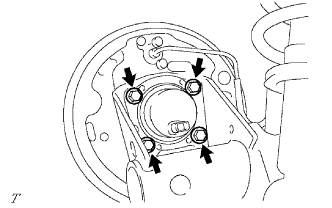 |
Install the parking brake plate and the axle hub and bearing to the rear axle beam with the 4 bolts.
| 4. INSTALL REAR AXLE HUB AND BEARING ASSEMBLY RH |
| 5. CONNECT REAR NO. 4 BRAKE TUBE |
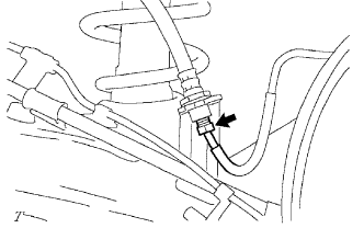 |
Temporarily tighten the rear brake tube and flexible hose.
Install the rear brake tube to the rear axle beam and secure it with the clip.
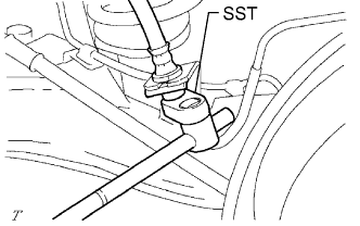 |
Fully tighten the rear brake tube using SST.
| 6. CONNECT REAR NO. 3 BRAKE TUBE |
| 7. INSTALL REAR STABILIZER BAR |
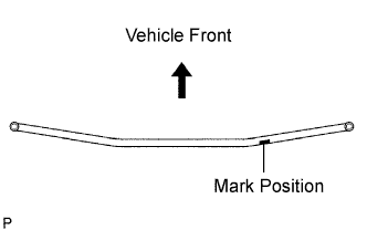 |
Install the stabilizer bar so that the mark position faces towards the vehicle's rear right. Hold the bolts and tighten the nuts.
| 8. INSTALL REAR AXLE BEAM DAMPER |
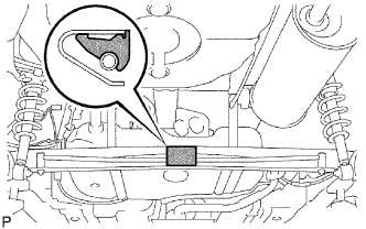 |
Install the rear axle beam damper to the center of the rear axle beam.
| 9. CONNECT SKID CONTROL SENSOR WIRE |
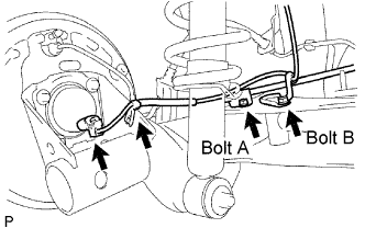 |
Install the skid control sensor wire and parking brake cable to the rear axle beam using the 2 bolts and clip.
| 10. INSTALL REAR BRAKE DRUM SUB-ASSEMBLY |
Aligning the matchmarks, install the rear brake drum.
| 11. INSTALL FRONT WHEEL |
Install the rear wheel.
| 12. STABILIZE SUSPENSION |
After jacking down the vehicle, bounce the vehicle up and down to stabilize the rear suspension.
| 13. FULLY TIGHTEN REAR AXLE BEAM ASSEMBLY |
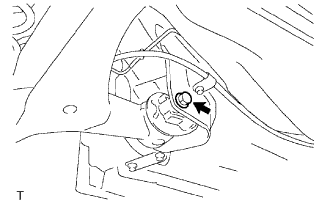 |
Hold the nut and rotate the bolt to fully tighten the rear axle beam on the LH side.
| 14. FULLY TIGHTEN REAR SHOCK ABSORBER WITH COIL SPRING |
|
Install the rear shock absorber with coil spring (lower side) and tighten the nut.
| 15. INSTALL REAR SENSOR CONNECTING BRACKET (w/ HID Headlight System) |
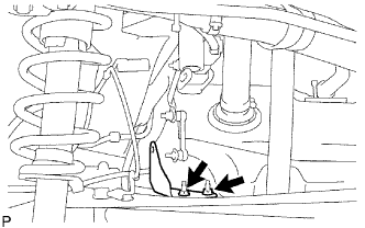 |
Install the sensor connecting bracket with the 2 nuts.
| 16. INSTALL REAR HEIGHT CONTROL SENSOR SUB-ASSEMBLY LH (w/ HID Headlight System) |
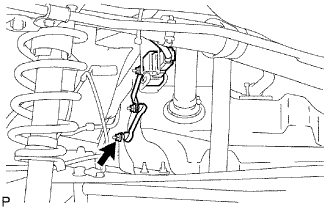 |
Install the height control sensor with the nut.
| 17. INSTALL FLOOR PANEL SIDE PLATE LH |
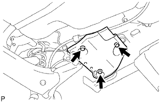 |
Install the floor panel side plate with the 3 bolts.
| 18. INSTALL FLOOR PANEL SIDE PLATE RH |
Install the floor panel side plate with the 3 bolts.
| 19. BLEED BRAKE LINE |
Bleed brake line (Click here).
| 20. INSPECT BRAKE FLUID |
| 21. INSPECT REAR WHEEL ALIGNMENT |
Inspect the rear wheel alignment (Click here).
| 22. PERFORM INITIALIZATION |
Perform the initialization (Click here).
| 23. ADJUST HEADLIGHT AIM ONLY |
Prepare the vehicle by performing the following.
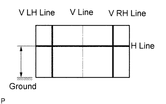 |
Prepare a piece of thick white paper (draw base lines).
V line (vehicle center position).
Draw a vertical line down the center of the paper to align with the center of the vehicle.
H line (headlight height).
Draw a horizontal line across the paper so that it is at the same height as the center mark of the low-beam light on the vehicle.
V LH line, V RH line (center mark position of right and left headlights).
Draw vertical lines on the left and right sides of the paper so that they line up with the center mark on the low-beam lights on the vehicle.
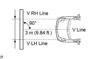 |
Check headlight aim
Align the paper and vehicle.
Start the engine.
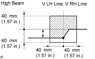 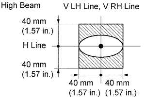 |
Turn on the headlight and check that the aim is within the specified range shown in the illustration.
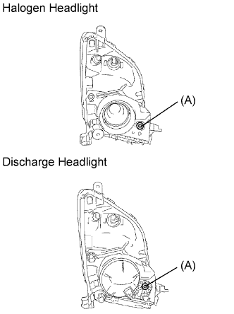 |
Adjust the aim in the vertical direction:
Using a screwdriver, adjust the headlight aim into the specified range by turning aiming screw A.
| 24. CHECK SPEED SENSOR SIGNAL |
Check the speed sensor signal (Click here).