 |
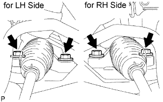
Install the steering gear from the left side of the vehicle.
- HINT:
- Be careful not to hit the stabilizer bar when installing the steering gear.
STEERING GEAR > INSTALLATION |
| 1. INSTALL STEERING GEAR ASSEMBLY |
|
Install the steering gear from the left side of the vehicle.
Install the No. 1 column hole cover to the steering gear.
Install the steering gear to the crossmember with the 4 bolts.
| 2. INSTALL STEERING INTERMEDIATE SHAFT |
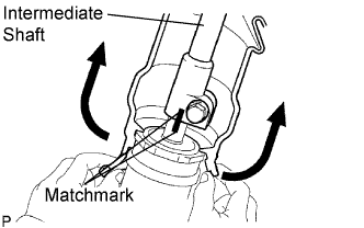 |
Move the No. 1 column hole cover to the upper side of the vehicle, align the matchmarks, and install the intermediate shaft from the inside of the vehicle.
Install the bolt.
Fit the recessed part on the No. 1 column hole cover to the steering gear.
| 3. INSTALL FRONT NO. 1 STABILIZER BRACKET LH |
Install the No. 1 stabilizer bracket the front suspension crossmember with the 2 bolts.
| 4. INSTALL FRONT NO. 1 STABILIZER BRACKET RH |
| 5. INSTALL FRONT STABILIZER LINK ASSEMBLY LH |
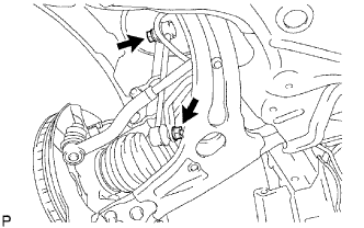 |
Install the front stabilizer link LH with the 2 nuts.
| 6. INSTALL FRONT STABILIZER LINK ASSEMBLY RH |
| 7. CONNECT NO. 1 TIE ROD END SUB-ASSEMBLY |
Connect the tie rod end to the steering knuckle and install it with the castle nut.
Install a new clip.
| 8. CONNECT NO. 2 TIE ROD END SUB-ASSEMBLY |
| 9. INSTALL FRONT WHEEL |
| 10. INSTALL NO. 1 STEERING COLUMN HOLE COVER SUB-ASSEMBLY |
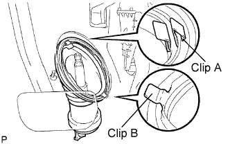 |
Install the clip labeled B to the vehicle body and install the No. 1 column hole cover to the vehicle body with the clip labeled A.
| 11. PLACE FRONT WHEELS FACING STRAIGHT AHEAD |
| 12. INSTALL STEERING SLIDING YOKE SUB-ASSEMBLY |
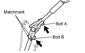 |
Align the matchmarks and install the sliding yoke to the intermediate shaft with the bolt labeled B.
Tighten the bolt labeled A.
| 13. INSTALL COLUMN HOLE COVER SILENCER SHEET |
| 14. CONNECT CABLE TO NEGATIVE BATTERY TERMINAL |
| 15. INSPECT AND ADJUST FRONT WHEEL ALIGNMENT |
Inspect and adjust the front wheel alignment (Click here).
| 16. PERFORM STEERING ANGLE SENSOR ZERO POINT CALIBRATION |