BACK DOOR > REASSEMBLY |
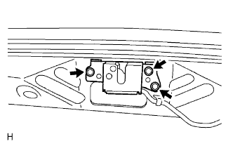
| 1. INSTALL BACK DOOR LOCK ASSEMBLY |
|
Install the door lock with the 3 bolts.
Adjust the door lock (Click here).
| 2. INSTALL BACK DOOR LOWER STOPPER |
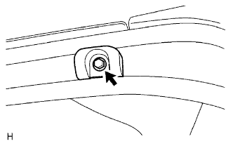 |
Install the stopper LH and RH with the 2 bolts.
| 3. INSTALL REAR DECK TRIM COVER |
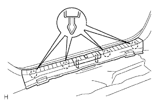 |
Attach the 4 claws to install the trim cover.
| 4. INSTALL BACK DOOR STAY ASSEMBLY LH |
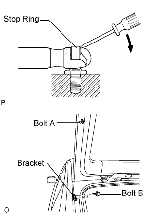 |
Using a screwdriver, remove the 2 stop rings and stay.
Remove the bolt labeled A from the door panel.
Remove the 2 bolts labeled B and stay bracket from the body panel.
| 5. INSTALL BACK DOOR STAY ASSEMBLY RH |
| 6. INSTALL BACK DOOR LOCK STRIKER ASSEMBLY |
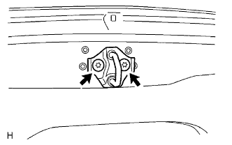 |
Using a T40 "torx" wrench, install the striker with the 2 screws.
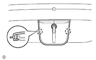 |
Attach the 2 claws to install the cover.
| 7. INSTALL LICENSE PLATE LIGHT ASSEMBLY |
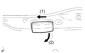 |
Remove the light as shown in the illustration.
Disconnect the connector.
Remove the bulb/socket unit from the light.
Remove the bulb from the socket.
| 8. INSTALL TELEVISION CAMERA ASSEMBLY |
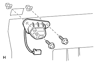 |
Connect the connector.
Install the camera with the 2 screws.
| 9. INSTALL BACK DOOR OUTSIDE GARNISH SUB-ASSEMBLY |
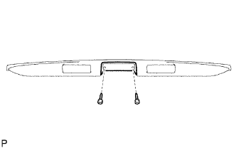 |
Install the back door opener switch to the garnish with the 2 screws.
Attach the 2 clips to install the garnish.
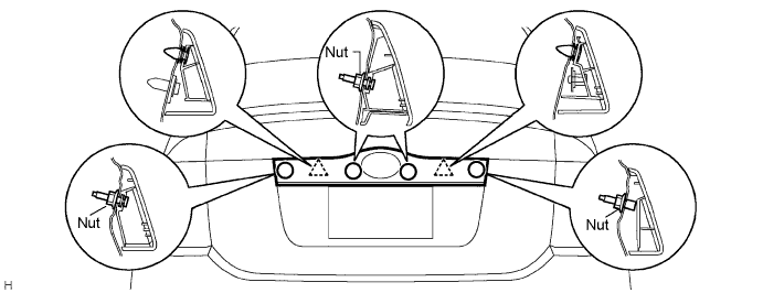
Install the 4 nuts.
Connect the back door opener switch connector.
| 10. INSTALL REAR SPOILER SUB-ASSEMBLY |
Large Type:
| Item | Temperature |
| Vehicle Body | 40 to 60°C (104 to 140°F) |
| Spoiler | 20 to 30°C (68 to 86°F) |
Put protective tape under the rear spoiler.
Using a heat light, heat the vehicle body surface and rear spoiler.
Remove the double-sided tape from the vehicle body and rear spoiler.
Wipe off any tape adhesive residue with cleaner.
Apply new double-sided tape to the rear spoiler.
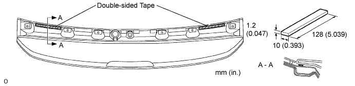
Using a heat light, heat the vehicle body and rear spoiler.
Remove the release paper from the rear spoiler.
Connect the center stop light connector.
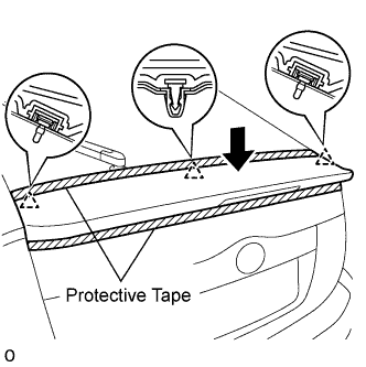 |
Attach the 3 clips to install the rear spoiler.
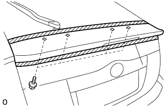 |
Install the 4 bolts.
| 11. INSTALL REAR WIPER MOTOR ASSEMBLY |
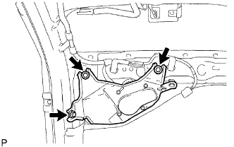 |
Install the rear wiper motor with the 3 bolts.
Connect the connector.
| 12. INSTALL BACK DOOR SIDE GARNISH RH |
Attach the 3 clips to install the garnish.
| 13. INSTALL BACK DOOR SIDE GARNISH LH |
Attach the 3 clips to install the garnish.
| 14. INSTALL BACK DOOR TRIM UPPER PANEL ASSEMBLY |
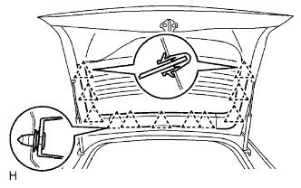 |
Attach the 11 clips to install the trim panel.
| 15. INSTALL BACK DOOR UPPER TRIM BOARD ASSEMBLY |
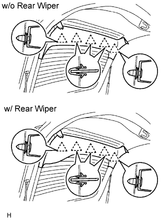 |
Attach the 5 clips to install the upper trim board.
| 16. INSTALL BACK DOOR LOWER TRIM BOARD ASSEMBLY |
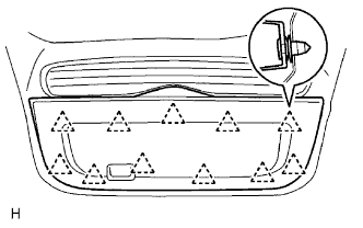 |
Attach the 11 clips to install the lower trim board.
| 17. INSTALL REAR WIPER ARM ASSEMBLY |
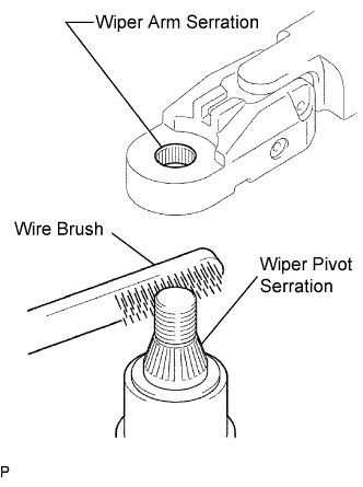 |
Stop the wiper motor at the automatic stop position.
Clean the wiper arm serration with a round file or equivalent.
Clean the wiper pivot serration with a wire brush.
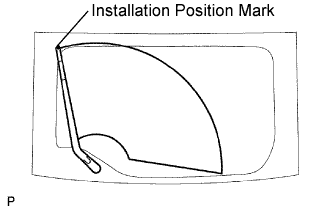 |
Install the arm and blade with the nut. Make sure that the arm and blade comes to the position shown in the illustration.
Install the cap.
| 18. CONNECT CABLE TO BATTERY NEGATIVE TERMINAL |
| 19. INSTALL NO. 3 REAR FLOOR BOARD |
| 20. INSTALL REAR DECK FLOOR BOX |
| 21. INSTALL NO. 2 REAR FLOOR BOARD |
| 22. INSPECT SRS WARNING LIGHT |
Inspect the SRS warning light (Click here).
| 23. PERFORM INITIALIZATION |
Perform initialization (Click here).