 |
Apply ATF to the spline of the inboard joint.
FRONT DRIVE SHAFT > INSTALLATION |
| 1. INSTALL FRONT DRIVE SHAFT ASSEMBLY LH |
|
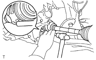
Apply ATF to the spline of the inboard joint.
Align the spline of the front drive shaft and insert the front drive shaft using a brass bar and hammer.
Install the front fender apron seal.
| 2. INSTALL FRONT DRIVE SHAFT ASSEMBLY RH |
| 3. INSTALL FRONT AXLE ASSEMBLY LH |
Push the front axle outward from the vehicle to align the spline of the front drive shaft with the front axle and insert.
| 4. CONNECT NO. 1 FRONT SUSPENSION ARM SUB-ASSEMBLY LOWER LH |
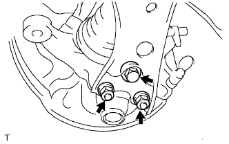 |
Push the No. 1 front suspension lower arm downward, install the front lower ball joint and tighten the bolt and 2 nuts.
| 5. CONNECT TIE ROD END SUB-ASSEMBLY LH |
Connect the tie rod end to the steering knuckle and install it with the castle nut.
Install a new clip.
| 6. INSTALL FRONT SPEED SENSOR LH |
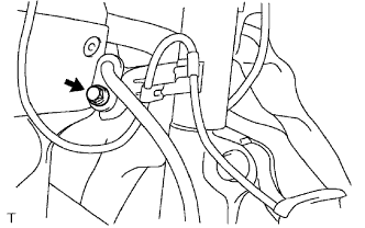 |
Connect the front speed sensor wire and flexible hose clamp to the shock absorber with the bolt.
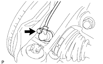 |
Install the front speed sensor to the steering knuckle.
| 7. INSTALL FRONT AXLE HUB NUT LH |
Clean the threaded parts on the drive shaft and axle hub nut using a non-residue solvent.
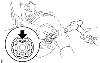 |
Using a 30 mm socket wrench, install a new hub nut.
Using a chisel and hammer, stake the hub nut.
| 8. INSTALL FRONT WHEEL |
| 9. ADD TRANSAXLE OIL |
| 10. INSPECT TRANSAXLE OIL |
Inspect transaxle oil (Click here).
| 11. INSPECT AND ADJUST FRONT WHEEL ALIGNMENT |
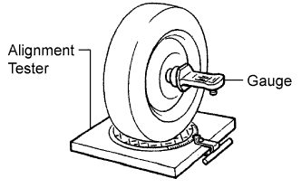 |
Put the front wheel on the center of the alignment tester.
Remove the center ornament.
Install the camber-caster-steering axis inclination gauge at the center of the axle hub or drive shaft.
Inspect the camber, caster and steering axis inclination.
| Item | Specified Condition |
| Camber Right-left error | -0° 35' +-45' (-0.58° +-0.75°) 45' (0.75°) or less |
| Caster Right-left error | 3° 10' +-45' (3.17° +-0.75°) 45' (0.75°) or less |
| Steering axis inclination Right-left error | 12° 35' +-45' (12.58° +-0.75°) 45' (0.75°) or less |
Remove the camber-caster-steering axis inclination gauge and attachment.
Install the center ornament.
If the caster and steering axis inclination are not within the specified values after the camber has been correctly adjusted, recheck the suspension parts for damage and/or wear.
| 12. CHECK ABS SPEED SENSOR SIGNAL |
Check the speed sensor signal (Click here).