HYBRID / BATTERY CONTROL HYBRID CONTROL SYSTEM DIAGNOSIS SYSTEM
DESCRIPTION
The power management control ECU has a self-diagnosis system. If the computer, hybrid control system, or a component is not working properly, the ECU records the conditions that relate to the fault. The ECU also illuminates the master warning light in the combination meter assembly and provides other appropriate messages on the multi-information display, such as the HV system warning message, the HV battery warning message, on the discharge warning message.
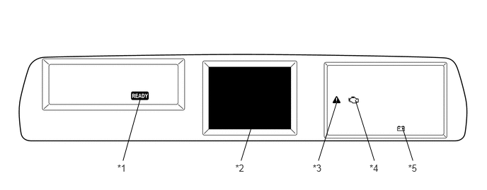
| *1 | READY Light | *2 | Multi-information Display |
| *3 | Master Warning Light | *4 | MIL |
| *5 | Auxiliary Battery Charging Warning Light | - | - |
- HINT:
-
The master warning light will illuminate when the hybrid control system malfunctions and the light will blink when in inspection mode.
2 TRIP DETECTION LOGIC
When a malfunction is first detected, the malfunction is temporarily stored in the power management control ECU memory (1st trip). If the same malfunction is detected during the next drive cycle, the MIL is illuminated (2nd trip).
FREEZE FRAME DATA
The power management control ECU records vehicle and driving condition information as freeze frame data the moment a DTC is stored. When troubleshooting, freeze frame data can be helpful in determining whether the vehicle was running or stopped, whether the engine was warmed up or not, as well as other data recorded at the time of a malfunction.
AUXILIARY BATTERY VOLTAGE
- Standard Voltage:
Switch Condition Specified Condition Power switch ON 11 to 14 V
If voltage is below 11 V, replace or recharge the auxiliary battery.
- NOTICE:
-
After turning the power switch off, waiting time may be required before disconnecting the cable from the negative (-) auxiliary battery terminal. Therefore, make sure to read the disconnecting the cable from the negative (-) auxiliary battery terminal notices before proceeding with work (See page General>INTRODUCTION>REPAIR INSTRUCTION>PRECAUTION).
MIL (Malfunction Indicator Lamp)
The MIL is illuminated when the power switch is first turned on (IG), before the READY indicator comes on.
When the READY indicator turns on, the MIL should turn off. If the MIL remains illuminated, the diagnosis system has detected a malfunction or abnormality in the system.
- HINT:
-
If the MIL is not illuminated when the power switch is first turned on (IG), check the MIL circuit (See page Engine / Hybrid System>1NZ-FXE (ENGINE CONTROL)>SFI SYSTEM (w/o Canister Pump Module)>MIL Circuit).