HYBRID / BATTERY CONTROL HYBRID CONTROL SYSTEM P0A90-251 Drive Motor "A" Performance
DESCRIPTION
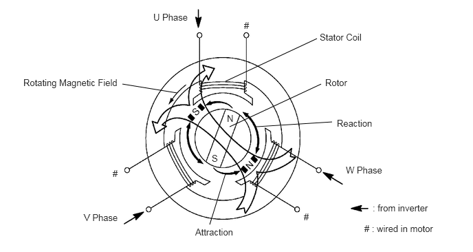
When three-phase alternating current flows through the three-phase windings of the stator coil, a rotating magnetic field is generated in motor. The system controls the rotation of the magnetic field in accordance with the rotating position and speed of the rotor. As a result, the permanent magnets provided in the rotor are pulled in the direction of rotation, generating torque. The generated torque is almost proportional to the amount of current. The system controls motor speed by regulating the frequency of the alternating current. Furthermore, the system properly controls the rotating magnetic field and the angle of the rotor magnets in order to generate high torque in an efficient manner, even at high speeds.
- HINT:
-
The term "drive motor A" indicates MG2.
| DTC No. | INF Code | DTC Detection Condition | Trouble Area |
|---|---|---|---|
| P0A90 | 251 | Motor magnetic force deterioration or same phase short circuit | ·
Hybrid vehicle transaxle assembly ·
Motor cable ·
Inverter with converter assembly ·
Wire harness or connector ·
Hybrid vehicle control ECU |
CAUTION / NOTICE / HINT
- CAUTION:
- ·
Before inspecting the high-voltage system, take safety precautions such as wearing insulated gloves and removing the service plug grip to prevent electrical shocks. After removing the service plug grip, put it in your pocket to prevent other technicians from accidentally reconnecting it while you are working on the high-voltage system.
·After removing the service plug grip, wait for at least 10 minutes before touching any of the high-voltage connectors or terminals. After waiting for 10 minutes, check the voltage at the terminals in the inspection point in the inverter with converter assembly. The voltage should be 0 V before beginning work (See page Engine / Hybrid System>HYBRID / BATTERY CONTROL>HYBRID CONTROL SYSTEM>PRECAUTION).
- HINT:
-
Waiting for at least 10 minutes is required to discharge the high-voltage capacitor inside the inverter with converter assembly.
- NOTICE:
-
After turning the power switch off, waiting time may be required before disconnecting the cable from the negative (-) auxiliary battery terminal. Therefore, make sure to read the disconnecting the cable from the negative (-) auxiliary battery terminal notices before proceeding with work (See page General>INTRODUCTION>REPAIR INSTRUCTION>PRECAUTION).
- HINT:
-
After the repair, clear the DTCs and perform the following procedure to check that DTCs are not output.
- 1.
Drive the vehicle until the cumulative traveling time driving a vehicle speed of 40 km/h (25 mph) or more is a few minutes. (It is not required to keep driving at 40 km/h (25 mph) or more.)
PROCEDURE
Connect the intelligent tester to the DLC3.
Turn the power switch on (IG).
Enter the following menus: Powertrain / Hybrid Control / DTC.
Check if DTCs are output.
- Result:
Result Proceed to Only P0A90-251 is output or P0A90-251 and DTCs other than the ones in the table below are also output. A Any of the following DTCs are also output. B
| DTC No. | Relevant Diagnosis |
|---|---|
| P06B0-163 | Sensor Power Supply "A" Circuit/Open |
| P06D6-511 | Sensor Reference Voltage "F" Circuit/Open |
| P06E6-164 | Sensor Power Supply "C" Circuit/Open |
| P0A1A-151, 166, 658, 791 | Generator Control Module |
| P0A1B-198, 786, 794 | Drive Motor "A" Control Module |
| P0A1D (all INF codes)*1 | Hybrid Powertrain Control Module |
| P0A3F-243 | Drive Motor "A" Position Sensor Circuit |
| P0A40-500 | Drive Motor "A" Position Sensor Circuit Range/Performance |
| P0A41-245 | Drive Motor "A" Position Sensor Circuit Low |
| P0A4B-253 | Generator Position Sensor Circuit |
| P0A4C-513 | Generator Position Sensor Circuit Range/Performance |
| P0A4D-255 | Generator Position Sensor Circuit Low |
| P0A51-174 | Drive Motor "A" Current Sensor Circuit |
| P0A78-202, 282 | Drive Motor "A" Inverter Performance |
| P0A90-509 | Drive Motor "A" Performance |
| P0A92-521 | Hybrid Generator Performance |
| P0A93-346 | Inverter Cooling System Performance |
| P0AA6 (all INF codes)*1 | Hybrid Battery Voltage System Isolation Fault |
| P0BEA-290 | Drive Motor "A" Phase V Current Sensor Circuit Range/Performance |
| P0BEE-298 | Drive Motor "A" Phase W Current Sensor Circuit Range/Performance |
| P0C19-306 | Drive Motor "A" Torque Delivered Performance |
| P0C76-523 | Hybrid Battery System Discharge Time Too Long |
| P0D2E-586 | Drive Motor "A" Inverter Voltage Sensor Circuit Range/Performance |
| P0D2F-266 | Drive Motor "A" Inverter Voltage Sensor Circuit Low |
| P0D30-267 | Drive Motor "A" Inverter Performance |
| P0E05-328 | Generator Phase V Current Sensor Circuit Range/Performance |
| P0E09-336 | Generator Phase W Current Sensor Circuit Range/Performance |
| P0E32-585 | DC/DC Converter Voltage Sensor "A" Range/Performance |
| P0E33-589 | DC/DC Converter Voltage Sensor "A" Low |
| P0E34-590 | DC/DC Converter Voltage Sensor "A" High |
| P0E71-344 | Generator Torque Delivered Performance |
| P1C2A-155 | Generator A/D Converter Circuit |
| P1C2B-192 | Drive Motor "A" A/D Converter Circuit |
| P1C2D-587 | Hybrid Battery Voltage / DC/DC Converter Voltage Correlation |
| P1C3C-294 | Drive Motor "A" Phase V Current Sensor Correlation |
| P1C3D-302 | Drive Motor "A" Phase W Current Sensor Correlation |
| P1C3E-333 | Generator Phase V Current Sensor Correlation |
| P1C3F-341 | Generator Phase W Current Sensor Correlation |
| P1C4A-288 | Drive Motor "A" Phase V Current Sensor Sub Circuit Range/Performance |
| P1C4F-296 | Drive Motor "A" Phase W Current Sensor Sub Circuit Range/Performance |
| P1C54-326 | Generator Phase V Current Sensor Sub Circuit Range/Performance |
| P1C59-334 | Generator Phase W Current Sensor Sub Circuit Range/Performance |
| P1C6D-501 | Drive Motor "A" Phase V Current Sensor Offset Range/Performance |
| P1C6E-502 | Drive Motor "A" Phase W Current Sensor Offset Range/Performance |
| P1C71-515 | Generator Phase V Current Sensor Offset Range/Performance |
| P1C72-516 | Generator Phase W Current Sensor Offset Range/Performance |
| P1C73-512 | Sensor Standard Voltage "F" Circuit/Open |
| P1CA6-156 | Generator Control Module Malfunction |
| P1CA7-193 | Drive Motor Control Module Malfunction |
| P1CAC-200 | Generator Position Sensor Angle Malfunction |
| P1CAD-168 | Drive Motor "A" Position Sensor Angle Malfunction |
| P1CAF-792 | Generator Position Sensor REF Signal Cycle Malfunction |
| P1CB0-795 | Drive Motor "A" Position Sensor REF Signal Cycle Malfunction |
| P1CB2-793 | Generator Position Sensor REF Signal Stop Malfunction |
| P1CB3-796 | Drive Motor "A" Position Sensor REF Signal Stop Malfunction |
| P3004-132 | High Voltage Power Resource |
| P3133-659 | Communication Error from Generator to Drive Motor "A" |
| P3134-661 | Communication Error from Drive Motor "A" to Generator |
| P3233-750 | Open or Short to B+ in Blocking of HV Gate Connection |
- HINT:
- ·
*1: If any INF codes are output for this DTC, refer to the corresponding diagnostic procedure.
·P0A90-251 may be output due to a malfunction which causes the DTCs in the table above to be output. In this case, first troubleshoot the output DTCs in the table above. Then, perform a reproduction test to check that no DTCs are output.
Turn the power switch off.
A
B
(See pageEngine / Hybrid System>HYBRID / BATTERY CONTROL>HYBRID CONTROL SYSTEM>DIAGNOSTIC TROUBLE CODE CHART)
Connect the intelligent tester to the DLC3.
Turn the power switch on (READY).
Test-drive the vehicle at a speed of 40 km/h (25 mph) for approximately 1 minute.
Enter the following menus: Powertrain / Hybrid Control / DTC.
Check if DTCs are output.
- Result:
Result Proceed to P0A90-251 is output or no DTC is output. A Any of DTCs other than P0A90-251 are outputt. B
Turn the power switch off.
A
B
(See pageEngine / Hybrid System>HYBRID / BATTERY CONTROL>HYBRID CONTROL SYSTEM>DIAGNOSTIC TROUBLE CODE CHART)
OK
NG
OK
NG
A
B
C
OK
NG
A
B
C
OK
NG
OK
NG
OK
NG