AXLE AND DIFFERENTIAL FRONT AXLE HUB REMOVAL
CAUTION / NOTICE / HINT
- NOTICE:
- ·
When the brake pedal is first depressed after replacing the brake pads or pushing back the disc brake piston, DTC C1214 may be output. As there is no malfunction, clear the DTC.
·While the auxiliary battery is connected, even if the power switch is off, the brake control system activates when the brake pedal is depressed or the door courtesy switch is turned on. Therefore, even if only brake shoes are to be removed and installed, be sure to perform the Disable Brake Control procedure and disconnect the cable from the negative (-) terminal of the auxiliary battery before beginning work.
- HINT:
- ·
Use the same procedure for the RH side and LH side.
·The procedure listed below is for the LH side.
PROCEDURE

 1. PRECAUTION
- NOTICE:
-
After turning the power switch off, waiting time may be required before disconnecting the cable from the negative (-) auxiliary battery terminal. Therefore, make sure to read the disconnecting the cable from the negative (-) auxiliary battery terminal notice before proceeding with work (See page General>INTRODUCTION>REPAIR INSTRUCTION>PRECAUTION).
2. DISABLE BRAKE CONTROL
3.REMOVE FRONT WHEEL
43502H
4.REMOVE FRONT AXLE SHAFT NUT
89543
5.SEPARATE FRONT SPEED SENSOR
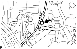
Remove the bolt and separate the front speed sensor wire and front flexible hose from the front shock absorber assembly.
- NOTICE:
-
Be sure to separate the front speed sensor from the front shock absorber assembly completely.
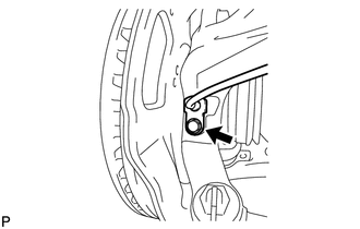
Remove the bolt and separate the front speed sensor from the steering knuckle.
- NOTICE:
- ·
Prevent foreign matter from contacting the sensor tip.
·Be careful not to damage the front speed sensor.
·Clean the speed sensor installation hole and the contact surfaces every time the speed sensor is removed.
6.SEPARATE FRONT DISC BRAKE CALIPER ASSEMBLY
43512
7.REMOVE FRONT DISC
45047
8.SEPARATE TIE ROD END SUB-ASSEMBLY
48069
9.SEPARATE FRONT LOWER NO. 1 SUSPENSION ARM SUB-ASSEMBLY
43420
10.SEPARATE FRONT DRIVE SHAFT ASSEMBLY
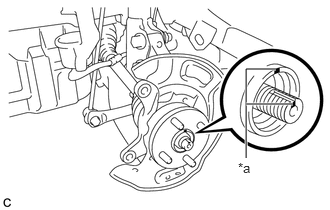
Put matchmarks on the front drive shaft assembly and front axle hub sub-assembly.
| *a | Matchmark |
Using a plastic hammer, separate the front drive shaft assembly from the front axle assembly. If it is difficult to separate, tap the end of the front drive shaft assembly using a brass bar and a hammer.
- NOTICE:
-
Be careful not to damage the drive shaft boot.
11.REMOVE FRONT AXLE ASSEMBLY
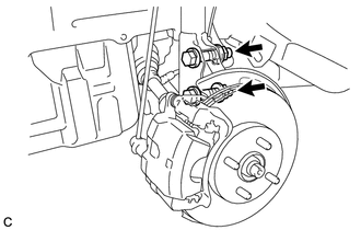
Remove the 2 bolts, 2 nuts and front axle assembly from the front shock absorber assembly.
- NOTICE:
- ·
When removing the nuts, keep the bolts from rotating.
·Be careful not to damage the drive shaft boot.
43502G
12.REMOVE FRONT AXLE HUB HOLE SNAP RING
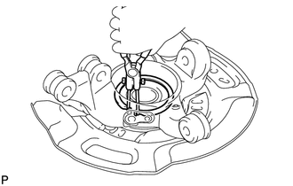
Using snap ring pliers, remove the axle hub hole snap ring.
- NOTICE:
-
When removing the hole snap ring, do not damage the magnetic rotor surface.
43502C
13.REMOVE FRONT AXLE HUB SUB-ASSEMBLY
Secure the front axle assembly between aluminum plates in a vise.
- NOTICE:
-
Do not overtighten the vise.
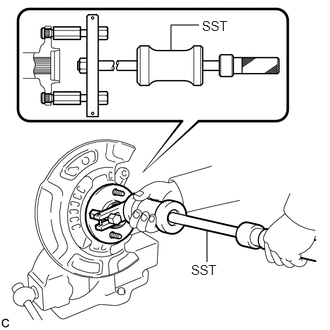
Using SST, remove the front axle hub sub-assembly.
- SST
- 09520-00031
- NOTICE:
-
Do not drop the front axle hub sub-assembly.
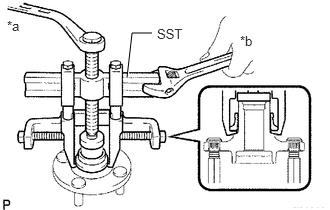
Using SST, remove the axle hub bearing inner race.
- SST
- 09950-40011 (09951-04020, 09952-04010, 09953-04020, 09954-04010, 09955-04011, 09957-04010, 09958-04011)
09950-60010 (09951-00370)
| *a | Turn |
| *b | Hold |
43502E
14.REMOVE FRONT AXLE HUB BEARING
Install the removed axle hub bearing inner race onto the outer side of the axle hub bearing.
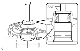
Using SST and a press, remove the axle hub bearing.
- SST
- 09223-15020
09387-02010
09950-60010 (09951-00630)
09950-70010 (09951-07100)