RM2170E
_55
Steering
_057026
POWER ASSIST SYSTEMS
_0278045
POWER STEERING SYSTEM
C
POWER ASSIST SYSTEMS POWER STEERING SYSTEM C1553/53 When Resetting Voltage, Vehicle is Being Driven
DESCRIPTION
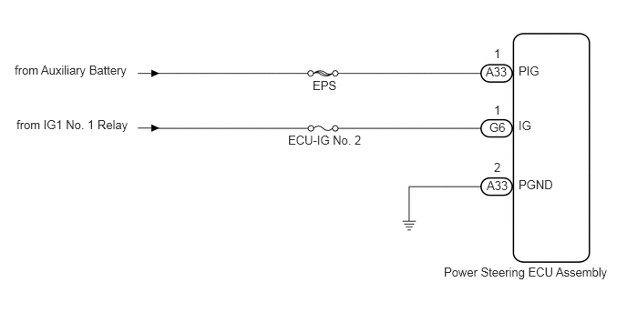
If the power steering ECU assembly determines that the motor power source voltage and the IG voltage are not within the specified range, it stops the power assist as a fail-safe function.
| DTC No. | DTC Detection Condition | Trouble Area |
|---|---|---|
| C1553/53 | ·
PIG power source overvoltage ·
IG power source overvoltage |
·
IG and PIG power source circuits ·
Power steering ECU assembly |
WIRING DIAGRAM
3.573,0.896 3.885,1.042
0.313,0.146
10
false
EPS
3.292,1.521 4.188,1.667
0.896,0.146
10
false
ECU-IG No. 2
5.552,0.74 5.823,0.906
0.271,0.167
10
false
A33
5.594,1.375 5.865,1.542
0.271,0.167
10
false
G6
5.927,0.729 6.198,0.896
0.271,0.167
10
false
PIG
5.927,1.354 6.104,1.521
0.177,0.167
10
false
IG
5.563,2.042 5.854,2.198
0.292,0.156
10
false
A33
5.927,2.031 6.385,2.188
0.458,0.156
10
false
PGND
5.073,3.031 7.146,3.208
2.073,0.177
10
false
Power Steering ECU Assembly
5.646,1.833 5.771,1.99
0.125,0.156
10
false
2
5.646,0.531 5.771,0.688
0.125,0.156
10
false
1
5.646,1.177 5.771,1.333
0.125,0.156
10
false
1
0.167,0.719 1.521,0.875
1.354,0.156
10
false
from Auxiliary Battery
0.188,1.344 1.563,1.5
1.375,0.156
10
false
from IG1 No. 1 Relay
CAUTION / NOTICE / HINT
- NOTICE:
-
If the power steering ECU assembly has been replaced with a new one, perform assist map writing and torque sensor zero point calibration (See page Steering>POWER ASSIST SYSTEMS>POWER STEERING SYSTEM>CALIBRATION).
PROCEDURE
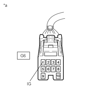
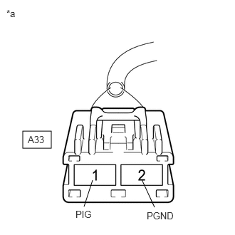
1.CHECK HARNESS AND CONNECTOR (IG, PIG)
a.
0.583,1.75 1,2
0.417,0.25
1.01,2.729 1.438,2.094
false
0.115,0.094 0.427,0.292
0.313,0.198
10
false
*a
0.688,1.792 1,1.99
0.313,0.198
10
false
G6
0.906,2.74 1.219,2.938
0.313,0.198
10
false
IG
0.333,1.917 0.75,2.167
0.417,0.25
2.26,3.031 2.073,2.625
false
1.229,3.021 1.354,2.635
false
0.094,0.115 0.406,0.313
0.313,0.198
10
false
*a
0.406,1.958 0.844,2.229
0.438,0.271
10
false
A33
2.146,3.073 2.667,3.344
0.521,0.271
10
false
PGND
1.104,3.052 1.625,3.323
0.521,0.271
10
false
PIG
Disconnect the connectors from the power steering ECU assembly.
b.
Measure the voltage according to the value(s) in the table below.
- Standard Voltage:
Tester Connection Condition Specified Condition G6-1 (IG) - A33-2 (PGND) Power switch on (IG) 9 to 16 V A33-1 (PIG) - A33-2 (PGND) Always 9 to 16 V
| *a | Front view of wire harness connector
(to Power Steering ECU Assembly) |
OK
REPLACE POWER STEERING ECU ASSEMBLY
NG
REPAIR OR REPLACE HARNESS OR CONNECTOR