HEATING / AIR CONDITIONING AIR CONDITIONING UNIT REASSEMBLY
PROCEDURE

 87050C
1.INSTALL NO. 1 AIR CONDITIONING RADIATOR DAMPER SERVO SUB-ASSEMBLY
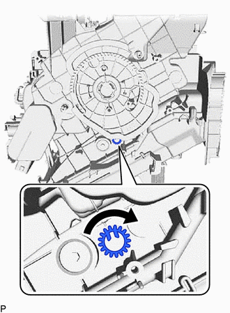
Turn the gear clockwise until it stops as shown in the illustration.
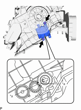
Using the reference points, install the No. 1 air conditioning radiator damper servo sub-assembly with the 2 screws.
| *a | Reference Point |
87050D
2.INSTALL NO. 2 AIR CONDITIONING RADIATOR DAMPER SERVO SUB-ASSEMBLY
When reusing the No. 2 air conditioning radiator damper servo sub-assembly:
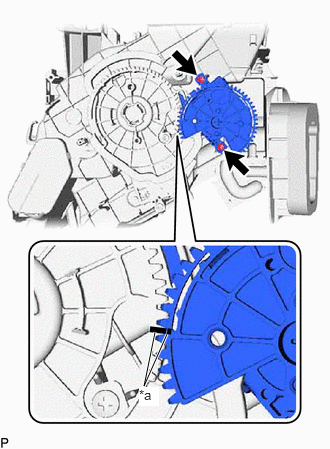
Align the matchmarks, install the No. 2 air conditioning radiator damper servo sub-assembly with the 2 screws.
| *a | Matchmark |
When installing a new No. 2 air conditioning radiator damper servo sub-assembly:
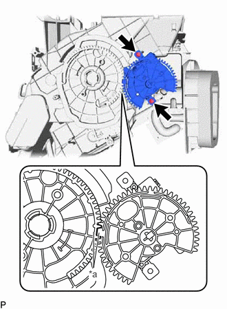
Using the reference points, install the No. 2 air conditioning radiator damper servo sub-assembly with the 2 screws.
| *a | Reference Point |
88539J
3.INSTALL DRAIN COOLER HOSE
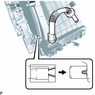
Align the drain cooler hose fitting and the protrusion of the lower heater case as shown in the illustration to connect the drain cooler hose to the heater case.
88625
4.INSTALL FRONT EVAPORATOR TEMPERATURE SENSOR (NO. 1 COOLER THERMISTOR)
88501
5.INSTALL NO. 1 COOLER EVAPORATOR SUB-ASSEMBLY
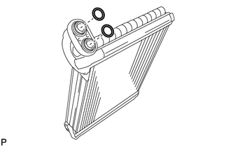
Sufficiently apply compressor oil to 2 new O-rings and the fitting surface of the No. 1 cooler evaporator sub-assembly.
- Compressor oil:
ND-OIL 11 or equivalent
Install the 2 O-rings to the No. 1 cooler evaporator sub-assembly.
- NOTICE:
-
Keep the O-rings and O-ring fitting surfaces free of foreign matter.
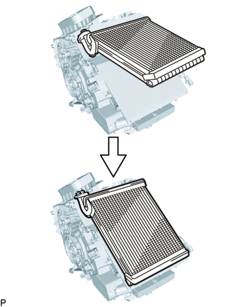
Install the No. 1 cooler evaporator sub-assembly with the No. 1 cooler thermistor to the upper heater case as shown in the illustration.
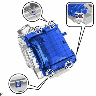
Engage the 4 claws and install the lower heater case.
Engage the clamp and connect the connector to the lower heater case.
for Type A:
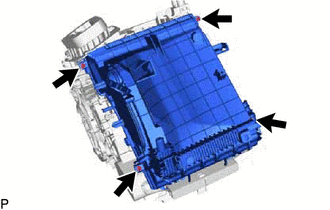
Install the 4 screws.
for Type B:
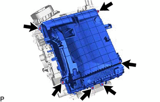
Install the 6 screws.
w/ Cover:
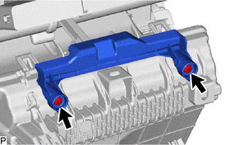
Install the cover sub-assembly with the 2 screws.
88515
6.INSTALL COOLER EXPANSION VALVE
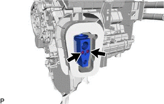
Using a 4 mm hexagon wrench, install the cooler expansion valve with the 2 hexagon bolts.
- Torque:
- 3.5 N*m (36 kgf*cm, 31 in.*lbf)
87107A
7.INSTALL HEATER RADIATOR UNIT SUB-ASSEMBLY
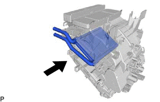
Install the heater radiator unit sub-assembly to the air conditioner radiator assembly.
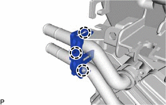
Engage the 3 claws and install the clamp.