Home › Vehicle Exterior › LIGHTING (EXT) › LIGHTING SYSTEM › 2014.12–2017.06
RM2170E _59 Vehicle Exterior _057049 LIGHTING (EXT) _0278196 LIGHTING SYSTEM J

LIGHTING (EXT)  LIGHTING SYSTEM  High Beam Headlight Circuit  


DESCRIPTION

When the main body ECU (multiplex network body ECU) receives a high beam turn on signal, the main body ECU (multiplex network body ECU) activates the bi-function by controlling the DIM/DRL relay. The bi-function increases the upper illumination area of the low beam by moving a shade using a solenoid built into the headlight assembly.

WIRING DIAGRAM
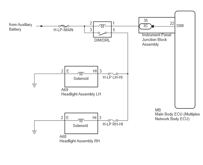
E308446E02
6.231,0.82 6.639,0.995 0.408,0.174 10 DIM 0.321,0.785 1.186,1.115 0.865,0.330 10 from Auxiliary Battery 5.476,3.946 7.148,4.543 1.672,0.597 10 Main Body ECU (Multiplex Network Body ECU) 5.998,0.735 6.172,0.910 0.175,0.174 10 22 5.054,0.82 5.279,0.995 0.224,0.174 10 3C 2.161,2.429 2.256,2.604 0.095,0.174 10 2 3.169,0.726 3.264,0.901 0.095,0.174 10 2 3.97,0.726 4.065,0.901 0.095,0.174 10 1 3.169,0.964 3.264,1.139 0.095,0.174 10 3 3.984,0.964 4.079,1.139 0.095,0.174 10 5 5.07,0.635 5.244,0.809 0.174,0.174 10 35 5.475,3.807 5.702,3.981 0.226,0.174 10 MB 3.63,2.645 4.415,2.820 0.785,0.174 10 H-LP LH-HI 2.595,2.69 3.204,2.864 0.609,0.174 10 Solenoid 1.891,0.973 2.637,1.148 0.746,0.174 10 H-LP-MAIN 3.33,1.333 3.951,1.532 0.622,0.199 10 DIM/DRL 3.625,4.306 4.429,4.480 0.804,0.174 10 H-LP RH-HI 2.163,3.083 2.516,3.258 0.353,0.174 10 A69 2.163,3.242 3.626,3.417 1.464,0.174 10 Headlight Assembly LH 2.102,4.74 2.951,4.915 0.849,0.174 10 A68 2.102,4.899 3.589,5.074 1.487,0.174 10 Headlight Assembly RH 5.018,1.144 6.088,1.690 1.071,0.546 10 Instrument Panel Junction Block Assembly 2.348,2.429 2.498,2.604 0.150,0.174 10 E 3.282,2.429 3.469,2.604 0.187,0.174 10 HI 3.511,2.429 3.605,2.604 0.095,0.174 10 3 2.149,4.078 2.244,4.252 0.095,0.174 10 2 2.336,4.078 2.486,4.252 0.150,0.174 10 E 3.27,4.078 3.457,4.252 0.187,0.174 10 HI 3.499,4.078 3.594,4.252 0.095,0.174 10 3 2.572,4.357 3.181,4.531 0.609,0.174 10 Solenoid

PROCEDURE

1.PERFORM ACTIVE TEST USING INTELLIGENT TESTER
a.

Connect the intelligent tester to the DLC3.


b.

Turn the power switch on (IG).


c.

Turn the intelligent tester on.


d.

Enter the following menus: Body / Main Body / Active Test.


e.

Perform the Active Test according to the display on the intelligent tester.

Main Body
Tester Display Test Part Control Range Diagnostic Note
Head Light Hi High beam headlights ON/OFF -

OK:

High beam headlights illuminate.


OK

PROCEED TO NEXT SUSPECTED AREA SHOWN IN PROBLEM SYMPTOMS TABLE

NG

2.INSPECT DIM/DRL RELAY
a.

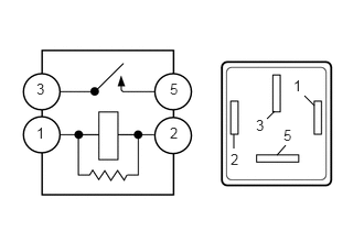
Remove the DIM/DRL relay from the No. 2 engine room relay block and No. 2 junction block assembly.

b.
E223988E02
2.594,1.052 2.521,1.125 false 2.208,1.271 2.208,1.406 false 2.615,1.469 2.698,1.375 false 2.969,1 2.875,0.906 false 0.344,0.76 0.552,1.01 0.208,0.25 10 3 0.344,1.177 0.625,1.448 0.281,0.271 10 1 1.604,0.76 1.865,0.99 0.26,0.229 10 5 1.604,1.177 1.844,1.458 0.24,0.281 10 2 2.677,1.198 2.865,1.417 0.188,0.219 10 5 2.177,1.427 2.427,1.677 0.25,0.25 10 2 2.417,1.104 2.615,1.354 0.198,0.25 10 3 2.771,0.729 3,0.979 0.229,0.25 10 1

Measure the resistance according to the value(s) in the table below.

Standard Resistance:
Tester Connection Condition Specified Condition
3 - 5 Voltage not applied between terminals 1 and 2 10 kΩ or higher
3 - 5 Voltage applied between terminals 1 and 2 Below 1 Ω


OK

3.CHECK HARNESS AND CONNECTOR (AUXILIARY BATTERY - DIM/DRL RELAY)

NG

REPLACE DIM/DRL RELAY

3.CHECK HARNESS AND CONNECTOR (AUXILIARY BATTERY - DIM/DRL RELAY)
a.

Measure the voltage according to the value(s) in the table below.

Standard Voltage:
Tester Connection Condition Specified Condition
Relay terminal 2 - Body ground Power switch off 11 to 14 V
Relay terminal 3 - Body ground Power switch off 11 to 14 V


OK

4.CHECK HARNESS AND CONNECTOR (DIM/DRL RELAY - HEADLIGHT ASSEMBLY LH AND HEADLIGHT ASSEMBLY RH)

NG

REPAIR OR REPLACE HARNESS OR CONNECTOR

4.CHECK HARNESS AND CONNECTOR (DIM/DRL RELAY - HEADLIGHT ASSEMBLY LH AND HEADLIGHT ASSEMBLY RH)
a.

Disconnect the A69 headlight assembly LH connector.


b.

Disconnect the A68 headlight assembly RH connector.


c.

Measure the resistance according to the value(s) in the table below.

Standard Resistance:
Tester Connection Condition Specified Condition
Relay terminal 5 - A69-3 (HI) Always Below 1 Ω
Relay terminal 5 - A68-3 (HI) Always Below 1 Ω
Relay terminal 5 - Body ground Always 10 kΩ or higher


OK

5.CHECK HARNESS AND CONNECTOR (DIM/DRL RELAY - INSTRUMENT PANEL JUNCTION BLOCK ASSEMBLY)

NG

REPAIR OR REPLACE HARNESS OR CONNECTOR

5.CHECK HARNESS AND CONNECTOR (DIM/DRL RELAY - INSTRUMENT PANEL JUNCTION BLOCK ASSEMBLY)
a.

Disconnect the 3C instrument panel junction block assembly connector.


b.

Measure the resistance according to the value(s) in the table below.

Standard Resistance:
Tester Connection Condition Specified Condition
Relay terminal 1 - 3C-35 Always Below 1 Ω
3C-35 - Body ground Always 10 kΩ or higher


OK

6.INSPECT INSTRUMENT PANEL JUNCTION BLOCK ASSEMBLY

NG

REPAIR OR REPLACE HARNESS OR CONNECTOR

6.INSPECT INSTRUMENT PANEL JUNCTION BLOCK ASSEMBLY
a.

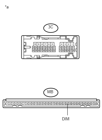
Remove the instrument panel junction block assembly (See page Power Source / Network>POWER DISTRIBUTION>MAIN BODY ECU>REMOVAL).

b.
U183663E01
0.164,0.144 0.364,0.331 0.200,0.187 10 *a 1.62,0.808 1.827,0.990 0.207,0.181 10 3C 1.592,2.976 1.831,3.140 0.239,0.164 10 MB 2.089,3.884 2.398,4.048 0.309,0.164 10 DIM 2.275,3.469 2.275,3.852 false

Remove the main body ECU (multiplex network body ECU) from the instrument panel junction block assembly.


c.

Measure the resistance according to the value(s) in the table below.

Standard Resistance:
Tester Connection Condition Specified Condition
3C-35 - MB-22 (DIM) Always Below 1 Ω


Text in Illustration
*a Component without harness connected
(Instrument Panel Junction Block Assembly)


OK

REPLACE MAIN BODY ECU (MULTIPLEX NETWORK BODY ECU)

NG

REPLACE INSTRUMENT PANEL JUNCTION BLOCK ASSEMBLY