P510 HYBRID TRANSMISSION / TRANSAXLE SHIFT LEVER INSTALLATION
PROCEDURE

 1.INSTALL SHIFT LEVER ASSEMBLY
Engage the 2 clamps and connect the instrument panel wire to the shift lever assembly.
Connect the 2 connectors to the shift lever assembly.
Temporarily install the shift lever assembly with the 4 bolts.
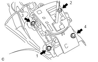
Fully tighten the 4 bolts in the order shown in the illustration.
- Torque:
- 12 N*m (122 kgf*cm, 9 ft.*lbf)
33820B
2.CONNECT TRANSMISSION CONTROL CABLE ASSEMBLY
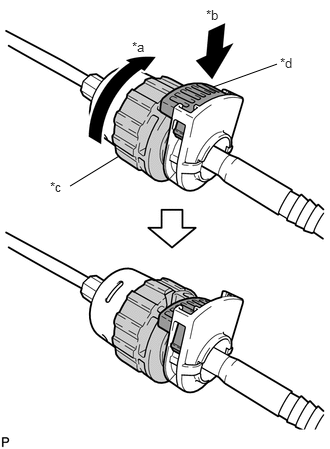
| *a | Rotate Approximately 180° |
| *b | Push In |
| *c | Nut |
| *d | Lock |
Rotate the nut of the transmission control cable approximately 180° in the direction shown in the illustration, and while holding the nut, push in the lock.
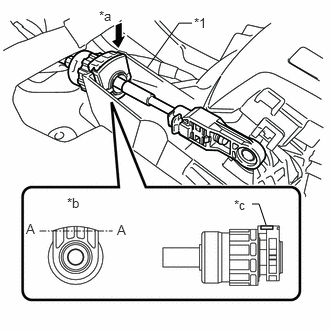
| *1 | Shift Lever Assembly |
| *a | Install |
| *b | Projecting Part |
| *c | Lock |
Install the transmission control cable assembly to the shift lever assembly.
- NOTICE:
- ·
Install the cable outer with the projecting part facing upwards.
·After installation, make sure that the cable outer lock is projecting from A as shown in the illustration.
·Check that the transmission control cable assembly is securely locked.
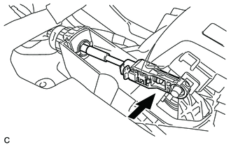
Confirm that the shift lever is in N, and then install the transmission control cable assembly to the shift lever assembly.
- NOTICE:
- ·
Securely install the cable end to the shift lever assembly.
·Install the cable end so that its adjustment lock section is on the driver side.
3.INSTALL REAR CONSOLE BOX ASSEMBLY
33504F
4.INSTALL SHIFT LEVER KNOB SUB-ASSEMBLY
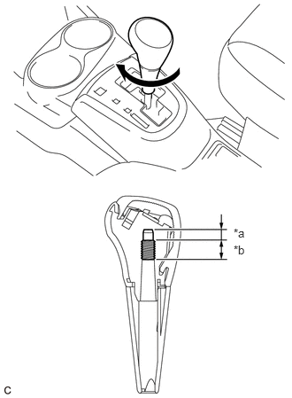
| *a | Non-threaded Part |
| *b | Threaded Part |
Turn the shift lever knob sub-assembly clockwise until it cannot be turned easily.
- HINT:
-
The shift lever knob sub-assembly will become difficult to turn when the lower shift lever assembly contacts the non-threaded part of the shift lever knob sub-assembly.
Turn the shift lever knob sub-assembly clockwise an additional 360° or more to install it as shown in the illustration.
- NOTICE:
-
Make sure to only turn the shift lever knob sub-assembly clockwise when adjusting the installation position.
33554C
5.INSTALL SHIFT LOCK RELEASE BUTTON COVER
Engage the 2 claws to install the shift lock release button cover to the position indicator housing.
6.INSPECT SHIFT LEVER POSITION
7.ADJUST SHIFT LEVER POSITION