INTERIOR PANELS / TRIM UPPER INSTRUMENT PANEL REASSEMBLY
PROCEDURE

 55359D
1.INSTALL NO. 5 INSTRUMENT PANEL CUSHION
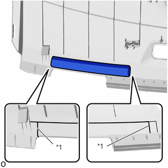
Align the marking lines on the upper instrument panel with the ends of a new No. 5 instrument panel cushion and install the No. 5 instrument panel cushion as shown in the illustration.
| *1 | Marking Line |
55349A
2.INSTALL INSTRUMENT PANEL CUSHION
Align the marking lines on the upper instrument panel with the ends of a new instrument panel cushion and install the instrument panel cushion as shown in the illustration.
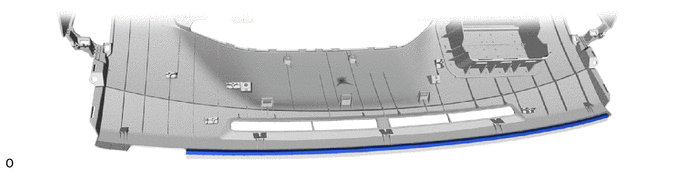
Align the marking lines on the upper instrument panel with the ends of the instrument panel cushion and install a new instrument panel cushion as shown in the illustration.
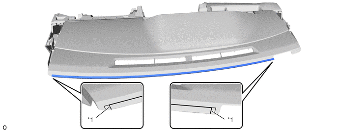
| *1 | Marking Line | - | - |
55356C
3.INSTALL NO. 2 INSTRUMENT PANEL CUSHION
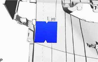
Using hot-melt glue, install a new No. 2 instrument panel cushion.
55355
4.INSTALL NO. 1 INSTRUMENT PANEL CUSHION
Using hot-melt glue, install 4 new No. 1 instrument panel cushions.

55381A
5.INSTALL FINISH PANEL MOUNTING BRACKET
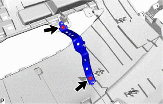
Install the finish panel mounting bracket with the 2 screws <B>.
- HINT:
-
Use the same procedure for the RH.
73960A
6.INSTALL INSTRUMENT PANEL PASSENGER AIRBAG ASSEMBLY (w/o Occupant Classification System)
73960A
7.INSTALL INSTRUMENT PANEL PASSENGER AIRBAG ASSEMBLY (w/ Occupant Classification System)
55972C
8.INSTALL NO. 2 SIDE DEFROSTER NOZZLE DUCT
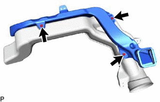
Install the No. 2 side defroster nozzle duct to the No. 2 heater to register duct with the 3 screws <B>.
55971C
9.INSTALL NO. 1 SIDE DEFROSTER NOZZLE DUCT
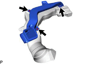
Install the No. 1 side defroster nozzle duct to the No. 1 heater to register duct with the 3 screws <B>.
10.INSTALL NO. 2 HEATER TO REGISTER DUCT ASSEMBLY
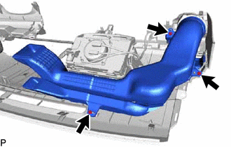
Install the No. 2 heater to register duct assembly with the 3 screws <B>.
11.INSTALL NO. 1 HEATER TO REGISTER DUCT ASSEMBLY
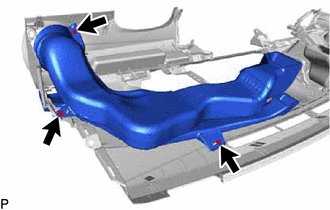
Install the No. 1 heater to register duct assembly with the 3 screws <B>.
55962
12.INSTALL NO. 2 SIDE DEFROSTER NOZZLE
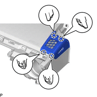
Engage the 4 claws to install the No. 2 side defroster nozzle.
55961
13.INSTALL NO. 1 SIDE DEFROSTER NOZZLE
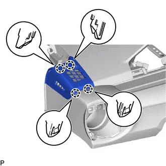
Engage the 4 claws to install the No. 1 side defroster nozzle.
55650
14.INSTALL NO. 1 INSTRUMENT PANEL REGISTER ASSEMBLY (for LHD)
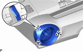
Engage the 3 clips to install the No. 1 instrument panel register assembly.
55660
15.INSTALL NO. 2 INSTRUMENT PANEL REGISTER ASSEMBLY (for RHD)
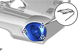
Engage the 3 clips to install the No. 2 instrument panel register assembly.