Home › Vehicle Exterior › WINDOW / GLASS › POWER WINDOW CONTROL SYSTEM › from 2017.06
RM2170E _59 Vehicle Exterior _057045 WINDOW / GLASS _0278147 POWER WINDOW CONTROL SYSTEM J

WINDOW / GLASS  POWER WINDOW CONTROL SYSTEM  Power Windows do not Operate Using All Window Switch  


DESCRIPTION

The power windows operate by using the power window regulator master switch assembly or power window regulator switch assemblies.

The power window regulator master switch assembly and each power window regulator switch assembly connect the same power supply and ground lines.

WIRING DIAGRAM

for LHD
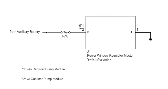

B479756E01
0.417,1.271 3.781,1.469 3.365,0.198 10 false from Auxiliary Battery 2.656,1.469 3.115,1.667 0.458,0.198 10 false P/W 3.375,1.177 3.833,1.375 0.458,0.198 10 false 7*2 3.375,1.01 3.833,1.208 0.458,0.198 10 false 6*1 3.708,1.292 3.865,1.49 0.156,0.198 10 false B 5.594,1.292 5.75,1.49 0.156,0.198 10 false E 5.823,1.177 5.979,1.375 0.156,0.198 10 false 1 3.719,2.125 4.031,2.323 0.313,0.198 10 false J1 3.719,2.292 5.75,3.208 2.031,0.917 10 false Power Window Regulator Master Switch Assembly 0.938,2.875 5.219,3.073 4.281,0.198 10 false *1: w/o Canister Pump Module 0.938,3.292 5.219,3.49 4.281,0.198 10 false *2: w/ Canister Pump Module


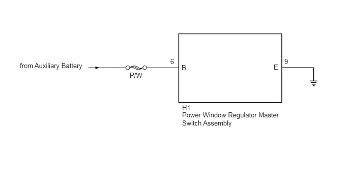
for RHD


B479756E02
0.406,1.26 3.771,1.458 3.365,0.198 10 false from Auxiliary Battery 2.656,1.458 3.115,1.656 0.458,0.198 10 false P/W 3.49,1.177 3.646,1.375 0.156,0.198 10 false 6 3.719,1.302 3.875,1.5 0.156,0.198 10 false B 5.604,1.292 5.76,1.49 0.156,0.198 10 false E 5.823,1.177 5.979,1.375 0.156,0.198 10 false 9 3.729,2.125 4.042,2.323 0.313,0.198 10 false H1 3.729,2.271 5.76,3.302 2.031,1.031 10 false Power Window Regulator Master Switch Assembly


CAUTION / NOTICE / HINT

NOTICE:

Inspect the fuses for circuits related to this system before performing the following inspection procedure.


PROCEDURE

1.CHECK HARNESS AND CONNECTOR (POWER WINDOW MASTER SWITCH ASSEMBLY - AUXILIARY BATTERY AND BODY GROUND)
a.

for LHD

i.

Disconnect the power window regulator master switch assembly connector.


ii.

Measure the voltage and resistance according to the value(s) in the table below.

Standard Voltage:
Tester Connection Condition Specified Condition
J1-6 (B) - Body ground*1
J1-7 (B) - Body ground*2
Power switch on (IG) 11 to 14 V


*1: w/o Canister Pump Module

*2: w/ Canister Pump Module


Standard Resistance:
Tester Connection Condition Specified Condition
J1-1 (E) - Body ground Always Below 1 Ω


b.

for RHD

i.

Disconnect the power window regulator master switch assembly connector.


ii.

Measure the voltage and resistance according to the value(s) in the table below.

Standard Voltage:
Tester Connection Condition Specified Condition
H1-6 (B) - Body ground Power switch on (IG) 11 to 14 V


Standard Resistance:
Tester Connection Condition Specified Condition
H1-9 (E) - Body ground Always Below 1 Ω


OK

2.REPLACE POWER WINDOW REGULATOR MASTER SWITCH ASSEMBLY

NG

REPAIR OR REPLACE HARNESS OR CONNECTOR

2.REPLACE POWER WINDOW REGULATOR MASTER SWITCH ASSEMBLY
a.

Replace the power window regulator master switch assembly.

Click hereVehicle Exterior>WINDOW / GLASS>POWER WINDOW MASTER SWITCH>REMOVAL


NEXT

3.CHECK POWER WINDOW CONTROL SYSTEM
a.

Check the power windows operation by using the power window regulator master switch assembly and power window regulator switch assemblies.

OK:

All power windows operate normally.


OK

END (POWER WINDOW REGULATOR MASTER SWITCH ASSEMBLY WAS DEFECTIVE)

NG

REPLACE MAIN BODY ECU (MULTIPLEX NETWORK BODY ECU)