HYBRID / BATTERY CONTROL HV BATTERY THERMISTOR INSTALLATION
PROCEDURE

 1.INSTALL HYBRID BATTERY THERMISTOR
- CAUTION:
-
Be sure to wear insulated gloves and protective goggles.
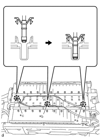
| *a | 1st Module from the Hybrid Battery Junction Block Assembly Side
(Wire harness color: Blue) |
| *b | 11st Module from the Hybrid Battery Junction Block Assembly Side
(Wire harness color: White) |
| *c | 20st Module from the Hybrid Battery Junction Block Assembly Side
(Wire harness color: Red) |
Engage the 3 claws of the hybrid battery thermistor (sensor portions) to install the hybrid battery thermistor to the HV battery.
- HINT:
-
Install each hybrid battery thermistor (sensor portion) to the appropriate location shown in the illustration.
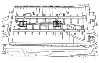
| *a | 8th Module from the Hybrid Battery Junction Block Assembly Side |
| *b | 18th Module from the Hybrid Battery Junction Block Assembly Side |
for 2 Clamps Type:
Engage the 2 clamps.
for 6 Clamps Type:
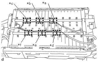
| *a | 9th Module from the Hybrid Battery Junction Block Assembly Side |
| *b | 13th Module from the Hybrid Battery Junction Block Assembly Side |
| *c | 17th Module from the Hybrid Battery Junction Block Assembly Side |
| *d | 8th Module from the Hybrid Battery Junction Block Assembly Side |
| *e | 12th Module from the Hybrid Battery Junction Block Assembly Side |
| *f | 16th Module from the Hybrid Battery Junction Block Assembly Side |
Engage the 6 clamps.
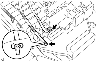
Connect the connector.
Engage the 2 claws to install the hybrid battery thermistor to the No. 1 hybrid battery cover intake duct.
2.INSTALL NO. 1 HYBRID BATTERY PACKING
3.INSTALL UPPER HYBRID BATTERY COVER SUB-ASSEMBLY
4.INSTALL NO. 2 HYBRID BATTERY SHIELD SUB-ASSEMBLY
5.INSTALL NO. 1 HYBRID VEHICLE BATTERY COVER PANEL LH
6.INSTALL BATTERY SMART UNIT