P410 HYBRID TRANSMISSION / TRANSAXLE SHIFT LEVER REMOVAL
PROCEDURE

 1. PRECAUTION
- NOTICE:
- ·
If the shift lock control unit assembly is to be replaced with a new one, it is necessary to clear the learned shift sensor voltage values by disconnecting and reconnecting the cable of the negative (-) auxiliary battery terminal.
·After turning the power switch off, waiting time may be required before disconnecting the cable from the negative (-) auxiliary battery terminal. Therefore, make sure to read the disconnecting the cable from the negative (-) auxiliary battery terminal notices before proceeding with work (See page General>INTRODUCTION>REPAIR INSTRUCTION>PRECAUTION).
58410B
2.REMOVE DECK BOARD ASSEMBLY
58411A
3.REMOVE NO. 1 DECK BOARD
58412A
4.REMOVE NO. 2 DECK BOARD
64993
5.REMOVE REAR DECK FLOOR BOX
64995
6.REMOVE DECK FLOOR BOX RH
7.DISCONNECT CABLE FROM NEGATIVE AUXILIARY BATTERY TERMINAL
- NOTICE:
-
When disconnecting the cable, some systems need to be initialized after the cable is reconnected (See page General>INTRODUCTION>REPAIR INSTRUCTION>INITIALIZATION).
8.REMOVE SHIFT LEVER KNOB
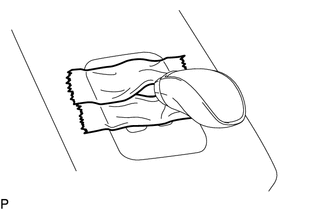
Apply protective tape around the shift lock control unit assembly.
- NOTICE:
-
As adhesive residue may fall when removing the shift lever knob, apply protective tape.
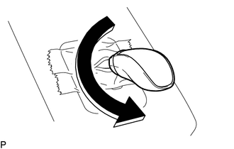
Turn the shift lever knob in the direction of the arrow in the illustration to remove it.
9.REMOVE INTEGRATION CONTROL AND PANEL
55431B
10.REMOVE UPPER INSTRUMENT PANEL FINISH PANEL
58810J
11.REMOVE CONSOLE BOX ASSEMBLY
12.REMOVE LOWER INSTRUMENT PANEL FINISH PANEL SUB-ASSEMBLY
33560
13.REMOVE SHIFT LOCK CONTROL UNIT ASSEMBLY
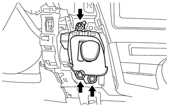
Remove the 3 nuts and separate the shift lock control unit assembly.
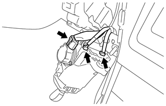
Disconnect the 3 connectors and remove the shift lock control unit assembly.