BRAKE SYSTEM (OTHER) BRAKE BOOSTER PUMP(for RHD) REMOVAL
PROCEDURE

 1. PRECAUTION
- NOTICE:
-
After turning the power switch off, waiting time may be required before disconnecting the cable from the negative (-) auxiliary battery terminal. Therefore, make sure to read the disconnecting the cable from the negative (-) auxiliary battery terminal notices before proceeding with work (See page General>INTRODUCTION>REPAIR INSTRUCTION>PRECAUTION).
2. DISABLE BRAKE CONTROL
3.REMOVE WINDSHIELD WIPER MOTOR AND LINK ASSEMBLY
55735C
4.REMOVE COWL BODY MOUNTING REINFORCEMENT RH
55701J
5.REMOVE OUTER COWL TOP PANEL SUB-ASSEMBLY
6.DRAIN BRAKE FLUID
51201
7.REMOVE FRONT SUSPENSION CROSSMEMBER SUB-ASSEMBLY
44595
8.REMOVE NO. 5 BRAKE ACTUATOR BRACKET
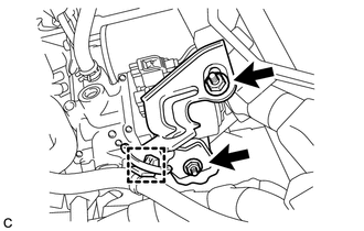
Separate the wire harness clamp.
Remove the 2 nuts and No. 5 brake actuator bracket.
9.REMOVE BRAKE BOOSTER PUMP ASSEMBLY WITH BRACKET
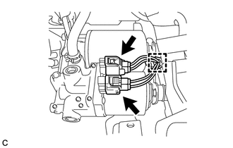
Disconnect the 2 connectors and separate the clamp from the brake booster pump assembly.
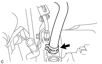
Move the clip and disconnect the No. 1 brake actuator hose from the brake booster pump assembly.
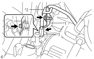
Remove the 2 bolts, No. 6 brake tube clamp and No. 1 brake tube clamp bracket.
| *1 | No. 1 Brake Tube Clamp Bracket |
| *2 | No. 6 Brake Tube Clamp |
| *3 | Front No. 1 Brake Tube |
Using a union nut wrench, disconnect the front No. 1 brake tube from the brake booster pump assembly.
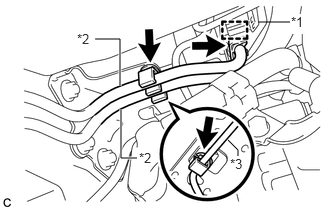
Disengage the clamp to separate the front No. 4 brake tube.
| *1 | Wire Harness Clamp |
| *2 | Fuel Line |
| *3 | Front No. 4 Brake Tube |
Separate the wire harness clamp and 2 fuel lines from the brake actuator bracket assembly.
- NOTICE:
-
Do not kink or damage the fuel lines.
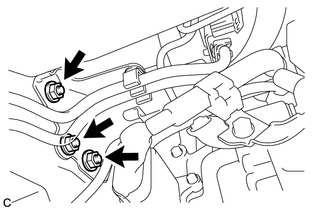
Remove the 3 nuts and brake booster pump assembly with bracket.
47070
10.REMOVE BRAKE BOOSTER PUMP ASSEMBLY
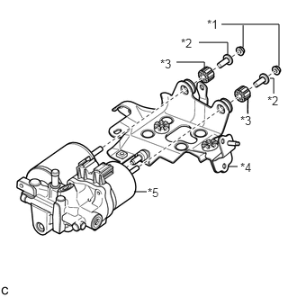
Remove the 2 nuts, 2 brake traction actuator bracket bushings, 2 brake actuator case collars and brake booster pump assembly from the brake actuator bracket assembly.
| *1 | Nut |
| *2 | Brake Actuator Case Collar |
| *3 | Brake Traction Actuator Bracket Bushing |
| *4 | Brake Actuator Bracket Assembly |
| *5 | Brake Booster Pump Assembly |