PARKING BRAKE PARKING BRAKE SYSTEM ADJUSTMENT
PROCEDURE

 1.INSPECT PARKING BRAKE PEDAL TRAVEL
Fully depress the parking brake pedal to engage the parking brake.
Depress the pedal again to release the parking brake.
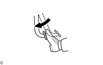
Slowly depress the parking brake pedal using the specified force, and count the number of clicks.
- Parking brake pedal travel:
8 to 11 notches at 300 N (31 kgf, 67.5 lbf)
If the parking brake pedal travel is not as specified, adjust the parking brake shoe clearance and parking brake pedal travel.
2.ADJUST PARKING BRAKE PEDAL TRAVEL (for LHD)
Remove the lower instrument panel finish panel assembly (See page Vehicle Interior>INTERIOR PANELS / TRIM>UPPER INSTRUMENT PANEL>REMOVAL).
Completely release the parking brake.
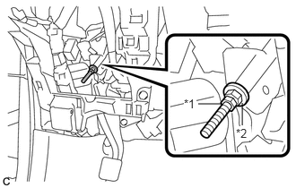
Loosen the lock nut and adjusting nut to completely release the parking brake cable.
| *1 | Lock Nut |
| *2 | Adjusting Nut |
Remove the rear wheels.
Temporarily install the hub nuts to the hub bolts.
- HINT:
-
Securely install the hub nuts to the rear disc.
Remove the parking brake shoe adjusting hole plug.
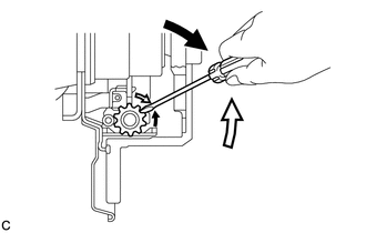
Turn the shoe adjuster and expand the shoes until the disc locks.

|
Expand |

|
Contract |
Turn and contract the shoe adjuster until the disc can rotate smoothly.
- Standard:
Returns 8 notches.
Check that there is no brake drag against the shoes.
Install the parking brake shoe adjusting hole plug.
Turn the adjusting nut until the parking brake pedal travel is corrected to be within the specified range.
- Parking brake pedal travel:
8 to 11 notches at 300 N (31 kgf, 67.5 lbf)
Using a wrench or an equivalent tool, hold the adjusting nut and tighten the lock nut.
- Torque:
- 7.0 N*m (71 kgf*cm, 62 in.*lbf)
Operate the parking brake pedal 3 to 4 times, and check the parking brake pedal travel.
Check that the parking brake does not drag.
Remove the hub nuts from the hub bolts.
Install the rear wheels.
- Torque:
- 103 N*m (1050 kgf*cm, 76 ft.*lbf)
Install the lower instrument panel finish panel assembly (See page Vehicle Interior>INTERIOR PANELS / TRIM>UPPER INSTRUMENT PANEL>INSTALLATION).
3.ADJUST PARKING BRAKE PEDAL TRAVEL (for RHD)
Remove the No. 1 instrument panel under cover sub-assembly.
- HINT:
-
Use the same procedure as for LHD (See page Vehicle Interior>INTERIOR PANELS / TRIM>LOWER INSTRUMENT PANEL>REMOVAL).
Remove the No. 1 air duct sub-assembly (See page Steering>STEERING COLUMN>STEERING COLUMN ASSEMBLY>REMOVAL).
Completely release the parking brake.
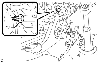
Loosen the lock nut and adjusting nut to completely release the parking brake cable.
| *1 | Lock Nut |
| *2 | Adjusting Nut |
Remove the rear wheels.
Temporarily install the hub nuts to the hub bolts.
- HINT:
-
Securely install the hub nuts to the rear disc.
Remove the parking brake shoe adjusting hole plug.
Turn the shoe adjuster and expand the shoes until the disc locks.
|
|
Expand |
|
|
Contract |
Turn and contract the shoe adjuster until the disc can rotate smoothly.
- Standard:
Returns 8 notches.
Check that there is no brake drag against the shoes.
Install the parking brake shoe adjusting hole plug.
Turn the adjusting nut until the parking brake pedal travel is corrected to be within the specified range.
- Parking brake pedal travel:
8 to 11 notches at 300 N (31 kgf, 67.5 lbf)
Using a wrench or an equivalent tool, hold the adjusting nut and tighten the lock nut.
- Torque:
- 7.0 N*m (71 kgf*cm, 62 in.*lbf)
Operate the parking brake pedal 3 to 4 times, and check the parking brake pedal travel.
Check that the parking brake does not drag.
Remove the hub nuts from the hub bolts.
Install the rear wheels.
- Torque:
- 103 N*m (1050 kgf*cm, 76 ft.*lbf)
Install the No. 1 air duct sub-assembly (See page Steering>STEERING COLUMN>STEERING COLUMN ASSEMBLY>INSTALLATION).
Install the No. 1 instrument panel under cover sub-assembly.
- HINT:
-
Use the same procedure as for LHD (See page Vehicle Interior>INTERIOR PANELS / TRIM>LOWER INSTRUMENT PANEL>INSTALLATION).
4.INSPECT BRAKE WARNING LIGHT
When operating the parking brake pedal, check that the brake warning light illuminates.
- Standard:
The brake warning light always illuminates at the first click.