STEERING COLUMN STEERING COLUMN ASSEMBLY REMOVAL
CAUTION / NOTICE / HINT
- NOTICE:
- ·
Do not replace the spiral cable with sensor sub-assembly with the negative (-) auxiliary battery cable connected and the power switch on (IG).
·Do not rotate the spiral cable with sensor sub-assembly without the steering wheel with the negative (-) auxiliary battery cable connected and the power switch on (IG).
·Ensure that the steering wheel is installed and aligned straight when inspecting the steering sensor.
·Do not remove the spiral cable from the steering sensor.
PROCEDURE

 1. PRECAUTION
- NOTICE:
-
Be sure to read Precaution thoroughly before servicing (See page Steering>STEERING COLUMN>STEERING SYSTEM>PRECAUTION).
2.ALIGN FRONT WHEELS FACING STRAIGHT AHEAD
45130
3.REMOVE HORN BUTTON ASSEMBLY
45100
4.REMOVE STEERING WHEEL ASSEMBLY
45286
5.REMOVE STEERING COLUMN COVER
- NOTICE:
-
Removing the steering column cover in the incorrect order will cause the parts to break.
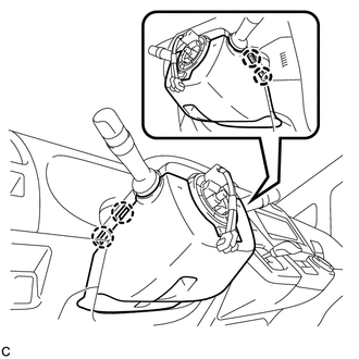
Push the right and left sides of the steering column cover (lower side) to disengage the 4 claws.
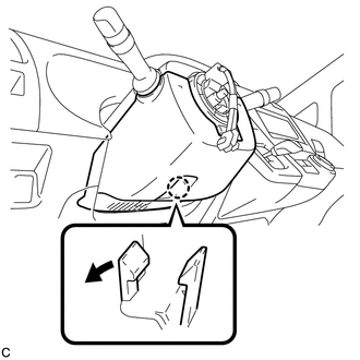
Insert fingers into the opening of the tilt lever of the steering column cover (lower side) to disengage the claw.
- NOTICE:
- ·
When disengaging the claw, be sure to expand only the part that faces the opening.
·Make sure that the claw has not become deformed or damaged as it may cause noise or poor installation of the steering column cover.
- HINT:
-
Applying a downward force to the shaded part shown in the illustration helps disengage the claw.
Using a screwdriver, insert the tip into each service hole to disengage the 2 claws to remove the steering column cover (lower side) as shown in the illustration.
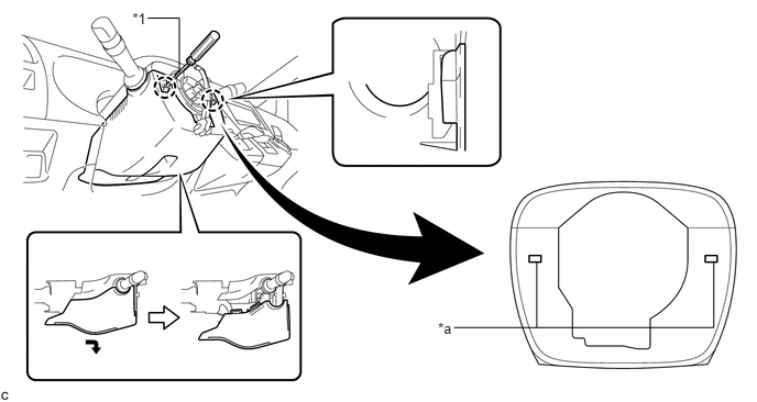
| *1 | Protective Tape | - | - |
| *a | Service Hole | - | - |
- NOTICE:
- ·
Tape the screwdriver tip before use.
·Make sure that the claw has not become deformed or damaged as it may cause noise or poor installation of the steering column cover.
- HINT:
-
Applying a downward force to the shaded part shown in the illustration with a screwdriver inserted into the service hole helps disengage the claw.
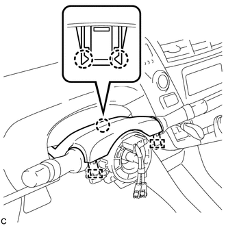
Disengage the 2 claws and 2 pins to remove the steering column cover (upper side).
6.REMOVE TURN SIGNAL SWITCH ASSEMBLY WITH SPIRAL CABLE SUB-ASSEMBLY
- NOTICE:
- ·
Do not replace the spiral cable with sensor sub-assembly with the negative (-) auxiliary battery cable connected and the power switch on (IG).
·Do not rotate the spiral cable with sensor sub-assembly without the steering wheel with the negative (-) auxiliary battery cable connected and the power switch on (IG).
·Ensure that the steering wheel is installed and aligned straight when inspecting the steering sensor.
·Do not remove the spiral cable from the steering sensor.
Disconnect the connectors from the turn signal switch assembly with spiral cable sub-assembly.
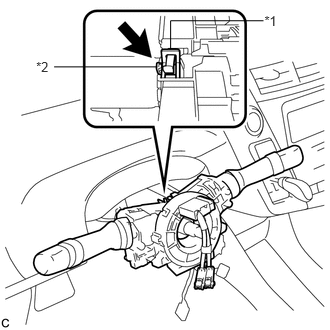
Using pliers, expand the clamp.
| *1 | Clamp |
| *2 | Claw |
While holding the clamp expanded, raise the claw using a screwdriver to disengage it, and then remove the turn signal switch assembly with spiral cable sub-assembly from the steering post assembly.
7.REMOVE BRAKE PEDAL SUPPORT ASSEMBLY (for LHD)
8.REMOVE BRAKE PEDAL SUPPORT ASSEMBLY (for RHD)
87201
9.REMOVE NO. 1 AIR DUCT SUB-ASSEMBLY (for LHD)
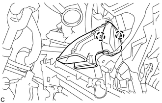
Disengage the 2 claws to remove the No. 1 air duct sub-assembly.
87201
10.REMOVE NO. 1 AIR DUCT SUB-ASSEMBLY (for RHD)
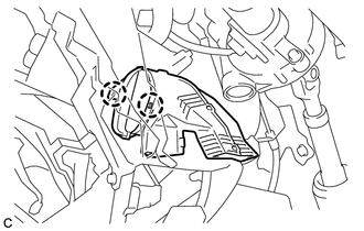
Disengage the 2 claws to remove the No. 1 air duct sub-assembly.
45259A
11.REMOVE COLUMN HOLE COVER SILENCER SHEET (for LHD)
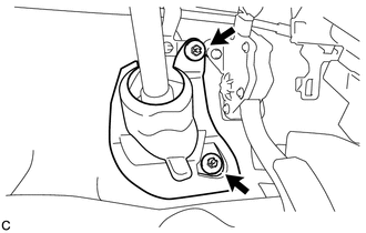
Turn back the floor carpet.
Remove the 2 clips and column hole cover silencer sheet.
45260
12.SEPARATE NO. 2 STEERING INTERMEDIATE SHAFT ASSEMBLY (for LHD)
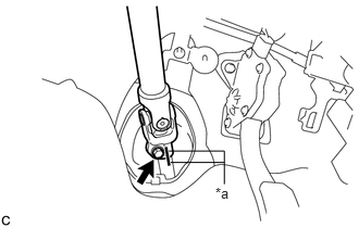
Put matchmarks on the No. 2 steering intermediate shaft assembly and the steering intermediate shaft.
| *a | Matchmark |
Remove the bolt and separate the No. 2 steering intermediate shaft assembly from the steering intermediate shaft.
13.REMOVE STEERING POST ASSEMBLY
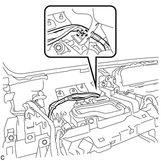
Disengage the wire harness clamp.
Disconnect each connector and disengage each wire harness clamp from the steering post assembly.
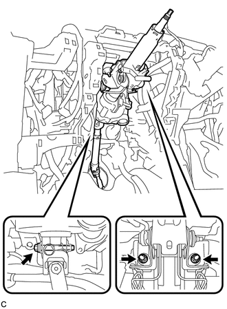
Remove the bolt, 2 nuts and steering post assembly.
45260
14.REMOVE NO. 2 STEERING INTERMEDIATE SHAFT ASSEMBLY
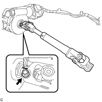
Put matchmarks on the No. 2 steering intermediate shaft assembly and steering column assembly.
| *a | Matchmark |
Remove the bolt and No. 2 steering intermediate shaft assembly from the steering column assembly.